Regional ITS Architecture Guide
Prepared by the
National ITS Architecture Team
Prepared for:
Intelligent Transportation Systems Joint Program Office (ITS JPO)
US Department of Transportation
Washington, DC 20590
Draft – May 28, 2020
Table of Contents
1 Regional ITS Architecture Overview
2 Regional ITS Architecture Definition
2.1 Purpose of a Regional ITS Architecture
2.2 US DOT Policy on Regional ITS Architecture
2.3 Components of Regional ITS Architecture
3 Regional Architecture Update/Development Approaches
3.2 Approach for New Architecture Development Effort
4.2 Why Maintain a Regional ITS Architecture
4.3 Who Is Involved in Architecture Maintenance Effort
4.4 Maintenance Roles and Responsibilities
4.5 When – the Architecture Update Timetable
4.6 What – Defining the Architecture Baseline
4.7 Maintenance Approach (How)
5 Regional ITS Architecture Use
5.1 Use in Long Range Transportation Planning
5.2 Use in Programming/ Budgeting
5.3 Use in Project Development
List of Figures
Figure 1. Regional ITS Architecture Components.
Figure 2. Regional ITS Architecture Scope
Figure 3. Architecture Scope in RAD-IT
Figure 4. New Mexico Regional and Statewide ITS Architecture Geographic Scopes
Figure 5. Denver Regional ITS Architecture Scope.
Figure 6. Regional ITS Architecture Components – Stakeholders
Figure 7. RAD-IT Stakeholders Tab
Figure 8. RAD-IT Output Tables Menu for Stakeholders
Figure 9. Stakeholder Output Example - Chicago
Figure 10. Regional ITS Architecture Components – Planning
Figure 11. Planning Tab in RAD-IT
Figure 12. RAD-IT Planning Example - Memphis
Figure 13. RAD-IT Planning Example - New York City
Figure 14. Regional ITS Architecture Components – Inventory
Figure 15. Grouping ITS Elements into General Inventory Items
Figure 16. Inventory Tab in RAD-IT
Figure 17. Example of an Inventory Summary from the Bay Area Regional ITS Architecture
Figure 18. Example of an Inventory Table from the Ohio Statewide ITS Architecture
Figure 19. Regional ITS Architecture Components - Services
Figure 20. Services Tab in RAD-IT
Figure 21. Service Package Based Diagram Example
Figure 22. Nevada Service Package Web Page Example
Figure 23. Nevada Service Package Web Page Diagram
Figure 24. Maricopa County Service Package Example
Figure 25. Regional ITS Architecture Components – Needs
Figure 26. Needs Tab in RAD-IT
Figure 27. Example Needs for the Memphis Regional ITS Architecture
Figure 28. Regional ITS Architecture Components – Roles & Responsibilities
Figure 29. ARC-IT Service Package Page
Figure 31. R&R Tab in RAD-IT Details
Figure 32. Alabama Statewide Architecture Operational Concept Example
Figure 33. Hawaii Statewide Architecture Operational Concept Example
Figure 34. Bay Area ITS Architecture Operational Concept Example
Figure 35. Regional ITS Architecture Components – Functions/Requirements
Figure 36. Functions Tab in RAD-IT
Figure 37. Functional Requirements Form in RAD-IT
Figure 38. Functional Objects Output Example
Figure 39. Functions Web Page Example
Figure 40. Functional Requirements Web Page
Figure 41. Regional ITS Architecture Components – Interfaces
Figure 42. Interfaces Tab in RAD-IT
Figure 43. Interfaces by Element Example
Figure 44. Interface Diagram Output Example.
Figure 45. Regional ITS Architecture Components – Standards
Figure 46. Communications Tab in RAD-IT
Figure 47. Standards Output Web Page Example.
Figure 48. Interfaces per Standards Output Example
Figure 49. Regional ITS Architecture Components – Agreements
Figure 50. Agreements Tab in RAD-IT
Figure 51. Portion of the Agreements for the Austin Regional ITS Architecture
Figure 52. Specific Agreement from Austin Regional ITS Architecture
Figure 53. Regional ITS Architecture Components – Projects
Figure 54. Start Tab from RAD-IT for Project Architectures
Figure 55. Example of Project Listing in a Regional Architecture
Figure 56. Project Information Detail from Regional Architecture Example
Figure 57. Stakeholder Identification and Involvement over Time
Figure 58. RAD-IT Main Screen Showing Tabs for Input
Figure 59. Approach for Change Identification
Figure 60. Regional ITS Architecture Usage in the Transportation Lifecycle
Figure 61. An Objectives-Driven, Performance-Based Approach to Planning for Operations
Figure 62. Operational Strategies to Support Regional Goals and Objectives
Figure 63. Project Initiative from Minnesota Statewide Architecture
Figure 64. ITS Architecture and ITS Strategic Plans
Figure 65. Metropolitan Transportation Commission TIP Report
Figure 66. NJTPA ITS Prioritization Criteria.
Figure 67. Traditional Project Development Approach
Figure 68. The "Vee" Diagram Approach to Systems Engineering
Figure 69. Regulations and Systems Engineering.
Figure 70. Using the Architecture to Support Systems Engineering
Figure 71. Using Project Architectures to Support Systems Engineering
Figure 72. Components of an ITS Architecture
Figure 73. Example Project Information from Bay Area ITS Architecture
Figure 74. Regional ITS Architecture Use for Concept of Operations
Figure 75. Interconnect diagram for Sample Project in SET-IT
Figure 76. Enterprise Diagram for Sample Project
Figure 77. Architecture Use in System Requirements Development
Figure 78. Project System Requirements Analysis
Figure 79. DMS Project Functional Requirements (Partial List)
Figure 80. Element Requirements Page from SET-IT
Figure 81. Architecture Use in Project Design
Figure 82. Transit Signal Priority Project ITS Standards
Figure 83. Sample Project Service Package Diagram..
Figure 84. Communications Stack from Sample Project
Figure 85. Example Architecture Use Checkpoints
Figure 86. Architecture and Location-Specific Projects
Figure 87. Project Architecture Start Tab in RAD-IT
Figure 88. Project Information for Sample Project in SET-IT
Figure 89. Project Architecture Stakeholders Tab in RAD-IT
Figure 90. Output Tables Menu in RAD-IT
Figure 91. Stakeholders Grid for Sample Project in SET-IT
Figure 92. Project Architecture User Needs Tab in RAD-IT
Figure 93. User Needs Definitions Grid in SET-IT
Figure 94. Project Architecture R&Rs Tab in RAD-IT
Figure 95. Roles & Responsibilities Output Tables Menu in RAD-IT
Figure 96. Stakeholder Roles Definitions Grid in SET-IT
Figure 97. Output Menu for Element Stakeholder Roles
Figure 98. Project Architecture Services Tab in RAD-IT
Figure 99. Service Packages Menu Screen in SET-IT
Figure 100. Service Package Diagram from SET-IT
Figure 101. Service Package Diagram from SET-IT (Enlarged)
Figure 102. Project Architecture Inventory Tab in RAD-IT
Figure 103. Output Menu for Element Inventory
Figure 104. Elements Definitions Grid in SET-IT
Figure 105. Service Package Diagram in SET-IT
Figure 106. Project Architecture Inventory Tab in RAD-IT
Figure 107. Information Flow Triples Definitions Grid in SET-IT
Figure 108. Project Architecture Agreements Tab in RAD-IT
Figure 109. Agreements Definitions Grid in SET-IT
Figure 110. Project Architecture Functions Tab in RAD-IT
Figure 111. Functional Requirements Details Screen from RAD-IT
Figure 112. Requirements Definitions Grid in SET-IT
Figure 113. Project Architecture Standards Tab in RAD-IT
List of Tables
Table 1. Candidate Stakeholders
Table 2. Stakeholder Descriptions - Austin Regional ITS Architecture
Table 4. Candidate Stakeholders/Participants
Table 5. Planning Factors to Goals
Table 6. Goals to Planning Factors
Table 7. ARC-IT Physical Information Flow Characteristics Legend
Table 8. Example Project Service Package Output Table
1 Regional ITS Architecture Overview
Rapid advances in information processing and communications technology have created new opportunities for transportation professionals to deliver safer and more efficient transportation services, and to respond proactively to increasing demand for transportation. However, many of these new opportunities are predicated upon effective coordination between organizations at both an institutional and technical level. To encourage and enable this coordination, the United States Department of Transportation (USDOT) has developed the Architecture Reference for Cooperative and Intelligent Transportation (ARC-IT), also known as the National Intelligent Transportation System (ITS) Architecture, and related tools to help identify and exploit these opportunities for cost-effective cooperation. This Regional ITS Architecture Guide is one such tool. It describes how to develop and use a regional ITS architecture, which is a cornerstone of planning for effective inter-agency coordination and for deployment and operation of technology-based projects.
1.1 Reader's Guide
This document has 2 major components:
1) Definition and Development of a Regional ITS Architecture – Chapters 2, 3, and 4 answer questions like, "What makes up a regional ITS architecture?" and "How is it developed, updated, and maintained?" Regional ITS Architecture Definition, will discuss the components that make up a regional architecture. Regional Architecture Update/Development Approaches, will describe the overall approaches of updating existing architectures versus developing a brand new architecture. Architecture Maintenance, will describe the effort to maintain an architecture and how to develop an architecture maintenance plan.
2) Using a Regional ITS Architecture – In chapter 5 we answer, "How can a regional ITS architecture be used to support transportation planning, both long term planning and programming of transportation projects?" and "How can a regional ITS architecture and its tools be used to support the development and definition of ITS projects?" Another section describes project ITS architectures from both the perspective of a regional ITS architecture and as part of a systems engineering analysis.
1.2 About the Icons
This document uses icons to highlight different kinds of information. The icons can help you find particular types of information within the document.

The "Tips" icon identifies suggestions that may improve the regional ITS architecture development effort or the quality of the products that are generated. Usually based on actual experience, these are ideas that have worked in the past.

The "Caution" icon flags warnings. In contrast to tips, these are problems that have been encountered that you should avoid. Also frequently based on actual experience, these are ideas that have NOT worked in the past.
 The "Resources" icon signals ITS resources that offer additional
information related to regional ITS architectures. Normally, a specific web
site address is provided for these resources. If you don't find the resources
you need here, the "DOT ITS Knowledge Resources" website is an excellent
general source of information. It is available on-line at https://www.itsknowledgeresources.its.dot.gov/its/itsbcllwebpage.nsf/KRHomePage.
The "Resources" icon signals ITS resources that offer additional
information related to regional ITS architectures. Normally, a specific web
site address is provided for these resources. If you don't find the resources
you need here, the "DOT ITS Knowledge Resources" website is an excellent
general source of information. It is available on-line at https://www.itsknowledgeresources.its.dot.gov/its/itsbcllwebpage.nsf/KRHomePage.
 The "Regulation" icon highlights references to the federal regulation on
ITS Architecture and Standards. These are normally specific references to
paragraphs that are most relevant to the particular process step or product. Additional
information on the regulation is available at: http://www.ops.fhwa.dot.gov/its_arch_imp/policy.htm.
The "Regulation" icon highlights references to the federal regulation on
ITS Architecture and Standards. These are normally specific references to
paragraphs that are most relevant to the particular process step or product. Additional
information on the regulation is available at: http://www.ops.fhwa.dot.gov/its_arch_imp/policy.htm.
 The "ARC-IT" icon identifies information about the National ITS Reference
Architecture, also known as the Architecture Reference for Cooperative and
Intelligent Transportation (ARC-IT). Specific information is provided on
different parts of the Architecture and how they apply to particular regional
ITS architecture development steps. Visit www.arc-it.net for more information.
The "ARC-IT" icon identifies information about the National ITS Reference
Architecture, also known as the Architecture Reference for Cooperative and
Intelligent Transportation (ARC-IT). Specific information is provided on
different parts of the Architecture and how they apply to particular regional
ITS architecture development steps. Visit www.arc-it.net for more information.
 The "Security" icon is used to flag security-related information in the
document. Security is an important factor to consider throughout the regional
ITS architecture development. Identified passages explain where security may
impact steps in the regional ITS architecture development process.
The "Security" icon is used to flag security-related information in the
document. Security is an important factor to consider throughout the regional
ITS architecture development. Identified passages explain where security may
impact steps in the regional ITS architecture development process.

 The RAD-IT and SET-IT icons are associated with
specific information on the RAD-IT and SET-IT software tools. Normally, the
passage explains how RAD-IT or SET-IT can be used to support a particular step
in the regional ITS architecture development process or in the use of the
architecture to support planning, programming of ITS projects, or development
of ITS.
The RAD-IT and SET-IT icons are associated with
specific information on the RAD-IT and SET-IT software tools. Normally, the
passage explains how RAD-IT or SET-IT can be used to support a particular step
in the regional ITS architecture development process or in the use of the
architecture to support planning, programming of ITS projects, or development
of ITS.
2 Regional ITS Architecture Definition
Intelligent Transportation Systems (ITS) have been defined as: "the application of advanced sensor, computer, electronics, and communication technologies and management strategies—in an integrated manner—to improve the safety and efficiency of the surface transportation system". This definition encompasses a broad array of systems and information processing and communications technologies. In order to fully incorporate ITS into the surface transportation network, ITS must be "mainstreamed" into the overall transportation planning and project development processes that exist in each state and metropolitan region of the country.
To support that effort a Regional ITS Architecture is developed as "a regional framework for ensuring institutional agreement and technical integration for the implementation of ITS projects or groups of projects". Regional ITS Architectures can be and have been developed and maintained by state departments of Transportation (DOTs) or by Metropolitan Planning Organizations (MPOs) or Council of Governments (COGs) for a region, district, or state. The concept of a regional ITS architecture was first defined in 23 CFR 940 on Intelligent Transportation System Architecture and Standards. See "US DOT Policy on Regional ITS Architecture" below for more about the federal regulations dealing with ITS.
2.1 Purpose of a Regional ITS Architecture
The purpose of developing a regional ITS architecture is to illustrate and document regional integration so that planning and deployment can take place in an organized and coordinated fashion. Typically, a region contains multiple transportation agencies and jurisdictions. These may have both adjoining and overlapping geographies, but the common thread for all of the agencies is the need to provide ITS solutions to transportation problems such as traffic congestion and safety hazards. It is important that these solutions be provided economically, utilizing public funds in a responsible manner.
Regional integration allows for the sharing of information and coordination of activities among regional transportation systems to efficiently and effectively operate. Regional integration may also have a synergistic effect on transportation systems, e.g. information from one system may be used by another system for a different purpose. An example of this would be transit Automated Vehicle Location (AVL) data being used by a freeway management center as probe data to obtain speed information on freeway segments traveled by the transit vehicles. A regional ITS architecture illustrates this integration and provides the basis for planning the evolution of existing systems and the definition of future systems that facilitate the integration over time.
2.2 US DOT Policy on Regional ITS Architecture
 Title 23 (Highways), Chapter I, Subchapter K, Part 940 of the United
States Code of Federal Regulations (CFR), is about "Intelligent
Transportation System Architecture and Standards." The Federal Highway
Administration (FHWA) refers to this as 23CFR940. Federal Transit
Administration (FTA) published the "National ITS Architecture Consistency
Policy for Transit Projects" that has the same wording as 23CFR940. The
purpose of the regulation or policy was to provide "policies and
procedures for implementing section 5206(e) of the Transportation Equity Act
for the 21st Century (TEA-21), Public Law 105-178, 112 Stat. 457, pertaining to
conformance with the National Intelligent Transportation Systems Architecture
and Standards." (from www.ecfr.gov - 23CFR940.1 Purpose)
Title 23 (Highways), Chapter I, Subchapter K, Part 940 of the United
States Code of Federal Regulations (CFR), is about "Intelligent
Transportation System Architecture and Standards." The Federal Highway
Administration (FHWA) refers to this as 23CFR940. Federal Transit
Administration (FTA) published the "National ITS Architecture Consistency
Policy for Transit Projects" that has the same wording as 23CFR940. The
purpose of the regulation or policy was to provide "policies and
procedures for implementing section 5206(e) of the Transportation Equity Act
for the 21st Century (TEA-21), Public Law 105-178, 112 Stat. 457, pertaining to
conformance with the National Intelligent Transportation Systems Architecture
and Standards." (from www.ecfr.gov - 23CFR940.1 Purpose)
ITS projects funded through the highway trust fund are required to conform to the National ITS Architecture and applicable standards. The intention of the regulation/policy is to foster the deployment of integrated regional ITS systems.
Because it is highly unlikely that the entire National ITS Architecture would be fully implemented by any single metropolitan area or state, the regulation requires that the National ITS Architecture be used to develop a "regional ITS architecture" that would be tailored to address the local situation and ITS investment needs. The region is defined by local participants and is based on the needs for information sharing and coordination. It can be a metropolitan area, a state, a multi-state area, or a corridor.
This guide makes frequent reference to the federal regulation requirements for regional ITS architectures, describing how the specific process steps and products relate to the regulation, usually referenced as 23CFR940. In addition to the regional ITS architecture requirements, the regulation also includes requirements for ITS Project Implementation and Project Administration, which are not addressed in detail by this document.
Further
information on the Intelligent Transportation System Architecture and Standards
regulation can be found at http://www.ops.fhwa.dot.gov/its_arch_imp/policy.htm.
The text of the regulation itself can be found on the US government electronic
Code of Federal Regulations (e-CFR) website
on or FHWA's and FTA's websites. See https://ops.fhwa.dot.gov/its_arch_imp/archrule_final_1.htm for highways and https://www.transit.dot.gov/research-innovation/national-its-architecture-consistency-policy-transit-projects for transit.
2.3 Components of Regional ITS Architecture
Regional ITS architectures have been developed in all 50 states and in every major metropolitan area over the past 2 decades. Many are now being updated and maintained by state and local agencies. They all tend to have similar components. Including each of the components provide complete coverage for the requirements of the Regulation and, in some cases, go beyond the letter of the regulation to ensure best practice and to support integration within the region.
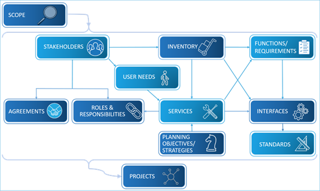
Figure 1. Regional ITS Architecture Components
The components that make up an architecture include:
- Connection of architecture to Regional Planning Goals, Objectives, and Strategies
- Operational Concept (Stakeholders' Roles and Responsibilities)
- System Functions and Requirements
- System Interfaces Supporting the Services
- Communications and Device Standards
- Interagency Agreements to support ITS services and projects
- Sequence of Regional ITS Projects
As shown in the figure above the scope of the architecture defines what will be included in each of the other components. Each of the components is connected to other parts of the architecture. Stakeholders are related to the Inventory, Agreements, and the Roles and Responsibilities. Inventory is connected to Functions/Requirements, Services/User Needs, and Interfaces. Functions are also related to Services and Interfaces. Services are also related to Roles and Responsibilities and Interfaces as well as Planning Objects/Strategies. Interfaces are also related to Standards. Projects are at the bottom to indicate that each component is implemented in a project.
The National ITS Architecture or the "Architecture Reference for Cooperative and Intelligent Transportation" (ARC-IT) is used as a template to create regional ITS architectures that are tailored for a specific state, metropolitan area, or other region of interest (e.g., a major corridor or a National Park). ARC-IT provides the fundamental building blocks: the physical objects, interfaces, service packages, user needs, and functions that are selectively included in the regional ITS architecture and customized as necessary to fully reflect the envisioned regional transportation system.
The regional ITS architecture defines the links between the pieces of the system and the information that is exchanged on each connection, and the ITS standards that can be used to support those connections. Over 300 regional ITS architectures have been developed so chances are good that you already have one in your region.
The approach for updating (if you already have a regional ITS architecture that has been created or updated in the not too distant past) or developing (if your region does not have an ITS architecture, or it was originally developed so long ago that you are essentially starting from scratch) is described at Regional Architecture Update/ Development Approach.
Once a Regional ITS Architecture has been created (or updated), it needs to be updated from time to time in order to capture the current plan for development of ITS in a region. A discussion of why an architecture needs to be updated as well as consideration of what should be updated and who should be involved in the update is described in Regional ITS Architecture Maintenance.
 A key tool in updating or developing regional ITS architectures is the Regional
Architecture Development for Intelligent Transportation (RAD-IT) software tool,
which allows regions to customize ARC-IT for a specific region. Each of the
component descriptions above includes a discussion about how that component is
expressed in RAD-IT. For more information about RAD-IT see the Resources/Tools page on the www.arc-it.net website.
A key tool in updating or developing regional ITS architectures is the Regional
Architecture Development for Intelligent Transportation (RAD-IT) software tool,
which allows regions to customize ARC-IT for a specific region. Each of the
component descriptions above includes a discussion about how that component is
expressed in RAD-IT. For more information about RAD-IT see the Resources/Tools page on the www.arc-it.net website.
2.3.1 Architecture Scope
The process of developing a regional ITS architecture begins with a definition of the region. The fundamental scope for the regional ITS architecture is established in this step.
2.3.1.1 Definition
Architecture Scope provides a description of the region for which an ITS architecture is developed. There are three dimensions to the scope: geographic, time horizon, and scope of services.
 Don't
invest too much time trying to define the region perfectly the first time. This
is an iterative process and the scope can be adjusted as the architecture
begins to take shape. Make a first cut and then update it as new stakeholders
are identified, new integration opportunities are considered, and the ultimate
uses for the architecture are understood.
Don't
invest too much time trying to define the region perfectly the first time. This
is an iterative process and the scope can be adjusted as the architecture
begins to take shape. Make a first cut and then update it as new stakeholders
are identified, new integration opportunities are considered, and the ultimate
uses for the architecture are understood.
2.3.1.2 Summary
|
Policy |
A "description of the region" is a required component of the regional ITS architecture as identified in 23CFR940.9(d)1 and FTA National ITS Architecture Policy Section 5.d.1.
|
|
Approach Key Activities |
If updating an existing regional ITS architecture: - Consider any needed updates to current scope definition o Has geographic area changed? o Has timeframe changed? o Have covered scope of services changed? - Has the scope of neighboring Regional ITS Architectures changed?
If defining a new regional ITS architecture: - Consider geographic scope o Review geographic boundaries of key stakeholders, major ITS projects and special "air quality conformity" issues o Consider the Metropolitan Planning Area boundary o Collect information on surrounding regional ITS architectures o Consider how this architecture will fit with others in the area - Define a time horizon for what will be included, e.g., 10 or 20 years - Determine the basic scope of the services that will be covered. For example, should this architecture address commercial vehicle services? - Review with preliminary scope with stakeholders and update as needed
|
|
INPUT Sources of Information |
- Geographic boundaries for key regional transportation projects - Stakeholder(s) agency "operational or service area" boundaries - The Long Range Transportation Plan ("the Plan") - Transportation Improvement Program (TIP) or Statewide TIP (or STIP) - Geographic boundaries of surrounding regional ITS architectures - Scope of overlapping regional ITS architectures
|
|
OUTPUT Results of Process
|
- A description of the region including geographic boundaries, timeframe, and scope of services.
|
2.3.1.3 Relationship to Other Components
The Architecture Scope sets the context for all of the other components shown below. The definition of geographic, timeframe, and scope of services informs the decisions made by developers regarding what stakeholders, elements, services, etc. to include in the architecture.

Figure 2. Regional ITS Architecture Scope
2.3.1.4 Approach
Whether this is an update to an existing architecture or the development of a completely new architecture the approach for the architecture's scope involves studying and deciding on what should be included in the architecture based on the geographic area, the time horizon, and the included services. The next sections describe the different activities involved in each approach.
2.3.1.4.1 Updating an Existing Architecture's Scope
Updating an existing regional ITS architecture begins with the consideration of whether the definition of the region has changed since the previous version of the architecture. Generally, the scope of a regional ITS architecture can be defined in three ways:
1) Define the geographic area covered by the architecture. What cities, counties, states, corridors, or other special areas does it include?
2) Define the planning timeframe or "time horizon" that the regional ITS architecture will address. Should the architecture encompass systems and services that are implemented over the next ten years, or twenty years?
3) Specify the general scope of services that are included. For example, should the architecture cover commercial vehicle services?
These three "dimensions" of the scope are explained in more detail below:
2.3.1.4.1.1 Geographic Area
Ideally, the previous geographic scope of a region was established so that it encompasses all systems that should be integrated together. In practice, it is sometimes difficult to determine where to draw the line so that the regional ITS architecture is inclusive without expanding to the point that the effort becomes unmanageable and consensus is difficult to achieve. While this is frequently called a "geographic" area, it is usually a political map that is being partitioned, defining a region along existing institutional boundaries.
The regulation states that metropolitan areas must consider the metropolitan planning area (MPA) as a minimum size for a region. The MPA is a good place to start since this boundary normally encompasses most integration opportunities and it coincides with the geographic region used for transportation planning. In practice, the MPA is the most commonly defined geographic region for metropolitan regional ITS architecture, but other geographic regions are sometimes defined.
For example, service boundaries or special conformity boundaries may have been a factor when determining the original regional boundary:
- Service Boundaries: Regional transportation agencies and other stakeholders each have geographic areas that they serve (e.g., transit services, toll authorities, etc.). In metropolitan areas, these service boundaries may go outside the metropolitan planning area and influence the regional ITS architecture boundary.
- Special Conformity Boundaries: In regions where there are special conformity issues like Air Quality, special conformity boundaries may also be considered. For example, ITS projects that are implemented to meet air quality goals within an air quality conformance boundary may require integration with other projects in the region. In this case the air quality conformance boundary may have been a consideration in establishing the previous geographic area covered by the regional ITS architecture.
When updating a regional ITS architecture, the most common reason to revise the geographic scope is because one or more of the factors discussed above in defining the original geographic scope has changed. One of the most common changes for a metropolitan architecture is that the MPA (often through expansion of the MPA) has been adjusted since the previous version. Sometimes additional counties (or portions of counties) are added to the MPA based on regional growth. In other cases, the creation of regional transportation authorities might impact the service boundary previously considered.
One final consideration for the geographic scope of the architectures is what other regional ITS architectures are adjoining or overlapping with the regional ITS architecture. For example, many states have created statewide ITS architectures that must be taken into account by the metropolitan area architecture(s) in those states. A few agencies have also created their own agency architectures that focus on internal agency interfaces, creating additional levels of architecture definition that should be taken into account in establishing architecture scope. It is not often that the existence of the other architectures will affect the geographic scope of the regional ITS architecture being updated, the other architectures may influence the service scope that is defined for the region.
 Special care is required when regional ITS architectures do overlap.
Caution should be used whenever the same ITS element or interface is included
in more than one regional ITS architecture. Unless automated methods like a
relational database or RAD-IT are used, it is almost certain that some
difference or ambiguity will arise in the two (or more) representations of the
same architecture definition. Whenever possible, it is a good idea to define
the ITS element or interface in one architecture and reference the one
"authoritative" definition in all other regional ITS architectures.
Special care is required when regional ITS architectures do overlap.
Caution should be used whenever the same ITS element or interface is included
in more than one regional ITS architecture. Unless automated methods like a
relational database or RAD-IT are used, it is almost certain that some
difference or ambiguity will arise in the two (or more) representations of the
same architecture definition. Whenever possible, it is a good idea to define
the ITS element or interface in one architecture and reference the one
"authoritative" definition in all other regional ITS architectures.
2.3.1.4.1.2 Time Horizon
The regional ITS architecture should look far enough into the future so that it serves its primary purpose of guiding the efficient integration of ITS systems over time. While there is no required minimum, the most appropriate timeframe should be established based on how the regional ITS architecture will be used. Making the timeframe too short reduces the value of the regional ITS architecture as a planning tool. Making the time horizon too long increases the effort involved in updating the architecture since a longer timeframe usually translates into expanded services and projects.
- 10-Year Horizon: A ten-year horizon is normally the shortest timeframe that should be considered as it is long enough to include most of the system integration opportunities that can be clearly anticipated by the region's stakeholders. This timeframe is sufficient to support Transportation Improvement Program (TIP) generation and guide project implementation.
- 20-Year Horizon: A 20-year time horizon is long enough to include all integration opportunities that may be included in the long-range Transportation Plan.
 Look at the long range plan
time horizon and consider that as a potential upper limit for the architecture.
Look at the long range plan
time horizon and consider that as a potential upper limit for the architecture.
When a regional ITS architecture is updated, the time horizon is normally carried over from the previous version, but if use of the architecture evolves with each update, then the time horizon may need to be reconsidered. In other words, the timeframe should be adjusted as necessary to match the vision of the stakeholders and the planned use of the architecture.
2.3.1.4.1.3 Service Scope
When an architecture is updated, the previous version has a defined service scope. This scope usually stays the same through each update, but as with the timeframe, if use of the architecture evolves or additional overlapping regional ITS architectures have been developed, then the scope of services may evolve as well. In general, the definition of scope of services is impacted based on the scope of other regional ITS architectures. For example, if a statewide ITS architecture is defining commercial vehicle services, the 511-traveler information system, and the electronic toll collection system for the state, then any other regional ITS architectures in the state may decide to reference the statewide architecture for these services.
Avoid defining the same ITS
services in multiple overlapping regional ITS architectures. The redundancy
will cause difficulty in maintaining regional ITS architectures so that they
are always consistent and complicate architecture use in the region.
2.3.1.4.2 Developing a New Architecture's Scope
Developing a regional ITS architecture for the first time begins with a definition of the region. The fundamental scope for the regional ITS architecture is established with the definition produced in this step. The general scope of a regional ITS architecture can be defined in three ways:
1) Geographic Area: Define the geographic area covered by the architecture. What cities, counties, states, corridors, or other special areas does it include?
2) Time Horizon: Define the planning timeframe that the regional ITS architecture will address. Should the architecture encompass systems and services that are implemented over the next five, ten, or twenty years?
3) Service Scope: Specify the general categories of services that are included. For example, should the architecture cover commercial vehicle services?
See the section on updating the scope of an existing architecture for more details about each of those 3 aspects of scope.
For a new architecture development this process will need to involve discussions among all of the core set of stakeholders discussed in the Stakeholders section. This discussion should start early to help decide who else needs to be involved in the process.
Don't invest too much time
trying to define the region perfectly the first time. Remember that developing
a regional ITS architecture is an iterative process, and the definition of the
region can be adjusted as the regional ITS architecture begins to take shape.
The stakeholders should make a first cut at defining the region and then update the geographic area, time horizon, and service scope as new stakeholders are identified, new integration opportunities are considered, and the ultimate uses for the regional ITS architecture are discussed in more detail.
2.3.1.5 RAD-IT
There is no separate tab in RAD-IT for architecture scope, but the basic scope information is contained on the Start tab as shown below.


Figure 3. Architecture Scope in RAD-IT
2.3.1.6 Examples
Architecture Scope descriptions are found in all architectures, usually in an architecture document, or on the home page of the website. The diagram below is taken from the New Mexico Statewide ITS Architecture and shows the geographic scope of the architecture (the state), but also shows the regional ITS architectures that have also been developed and interface with the statewide architecture.

Figure 4. New Mexico Regional and Statewide ITS Architecture Geographic Scopes
Below is an example of a scope description from the website for the Denver Regional Council of Governments (DRCOG) Regional ITS Architecture.

Figure 5. Denver Regional ITS Architecture Scope
2.3.2 Stakeholders
The success of the regional ITS architecture depends on the participation by a diverse set of stakeholders. This section discusses the stakeholders in a typical regional surface transportation system and discusses how to encourage their participation in the process.
2.3.2.1 Definition
Stakeholders are the agencies and organizations that own, operate, maintain or use the ITS systems in the region as well as other agencies/ authorities/ other-entities that have an interest in regional transportation issues (e.g., MPOs, etc.). This includes both public and private organizations.
2.3.2.2 Summary
|
Policy
|
Identification of participating agencies and other stakeholders as required in 23CFR940.9(d)2 and FTA National ITS Architecture Policy Section 5.d.2.
|
|
Approach Key Activities
|
If updating an existing regional ITS architecture: - Gather data on stakeholder changes in region o Interview core stakeholders - Update stakeholder information in the architecture o Revise information in RAD-IT - Review changes with stakeholders
If defining a new regional ITS architecture: - Identify core stakeholders - Identify full set of stakeholders o Review broad list with core stakeholders. o Look outside immediate peers to identify new stakeholders. - Review with stakeholders o Prepare educational materials o Outreach to stakeholders o Use ITS working groups already in place to engage potential stakeholders. o Obtain broad-based buy in and support from stakeholders.
|
|
INPUT Sources of Information |
- ITS educational and outreach resources - Existing working group rosters, various participant lists - Key stakeholder representatives from local transportation departments (cities, counties, states), public safety agencies and private companies
|
|
OUTPUT Results of Process
|
- Identification of participating agencies and other stakeholders |
2.3.2.3 Relationship to other components
As shown in the figure below, stakeholders are mapped to several other components of the Regional ITS Architecture. Each element in an inventory has an associated stakeholder(s). Roles and responsibilities are organized by stakeholders. Stakeholders also have user needs that are included in the architecture by way of the services they choose. Once interfaces are identified between agencies then agreements are necessary between different stakeholders. Projects, which really represents a subset of the above set of components for a single project, also are defined by which stakeholder funds, develops, operates and maintains the system deployed by the project. In addition, a variety of stakeholders may participate in a project by providing information to or receiving information from the systems deployed.

Figure 6. Regional ITS Architecture Components – Stakeholders
Considering the way stakeholders' names will be listed will make it easier to access and understand other parts of the architecture. The key information about Stakeholders is usually described by a table or the stakeholder page on the website. A recommendation is that agencies of similar nature are described in a consistent manner. For example, the various municipalities might each be named "City of xxx", while the counties might be named "yyy County." If departments are called out separately, then the agency name should be used to group departments for a given agency, e.g., City of xxx Public Works Department. This allows the stakeholders to more easily see their relevant information.
2.3.2.4 Approach
Whether this is an update to an existing architecture or the development of a completely new architecture the approach for the architecture's stakeholders involves ensuring the right stakeholders are involved in each step of the process and that the set of stakeholders is as inclusive as possible. The next sections describe the different activities involved in each approach.
- Developing Initial List of Stakeholders
2.3.2.4.1 Updating an Existing Architecture's Set of Stakeholders
In an Architecture Update, stakeholders play a key role in providing data for the update and reviewing the drafts and finalizing the outputs. Every region has a core group of stakeholders that would have been involved in the previous update(s) and will play a role in any update.
Core stakeholders represent key transportation agencies in the region who plan, deploy and maintain ITS systems. They are most commonly traffic, transit and maintenance groups at the state, county or municipal level. It is desirable to have public safety agencies part of the core stakeholders, but they are often not as heavily involved in the update process. Core stakeholders are often a part of ITS committees or technical groups that meet on a periodic basis. These meetings serve as excellent venues for meetings throughout the architecture update. The basic activities in updating stakeholders are given below.
2.3.2.4.1.1 Gather Data on Stakeholder Changes in Region
Some changes occur in the stakeholders in almost every update. One of the key ways to gather these changes is to interview the stakeholders (likely the core stakeholders plus a few key others as appropriate) to find out what changes have occurred since the previous update. One of the common changes that occurs is that the name or description of the stakeholder has changed since the last update. This often occurs because agencies change names or responsibilities over time. This is particularly true if the stakeholder names in the architecture are broken down to the departments within an agency (e.g. Public Works Department, vs agency name alone). In addition, new stakeholders may have come to the table and need to be included in the architecture.
2.3.2.4.1.2 Update Stakeholder information in the architecture
The architecture as previously defined will have a list of stakeholders that will serve as the starting point for the update. The primary updates relating to stakeholder are done on the Stakeholder tab of RAD-IT, where the names and descriptions are contained (see description of the Stakeholder Tab below). The changes determined in the previous activity should be entered into the RAD-IT file.
2.3.2.4.1.3 Review Changes with Stakeholders
Once the changes are defined, they need to be reviewed by the relevant stakeholders to obtain concurrence on the changes. The review will usually be done with a table of stakeholders or via the relevant section of an architecture website.
2.3.2.4.2 Developing a New Architecture's List of Stakeholders
In a new Architecture development, the stakeholders in the regional surface transportation system are identified and the process of encouraging their participation in the regional ITS architecture development is initiated. This effort usually begins by identifying a core group of stakeholders who will be key participants in the architecture development.
2.3.2.4.2.1 Identify Core Stakeholders
Each architecture development needs a set of core stakeholders that will play a key role in the development over the architecture. This core stakeholder group usually includes the planners and operations staff from the primary transportation agencies in the region. This usually includes key transportation agencies at the state, county or municipal level. This core group provides continuity to the development effort and an important set of contacts for the organization that is responsible for the architecture development and the architecture developer(s). Including too many stakeholders at the start can hinder regional ITS architecture development progress and discourage people with limited vested interest in the process. Although the architecture effort should be very inclusive, a region may have better initial success if they are able to build consensus among the stakeholders that plan/own/operate ITS systems first before adding others into the decision making process.
2.3.2.4.2.2 Identify Full Set of Stakeholders:
The core stakeholder group usually works with the responsible organization and the architecture developers to identify the wider range of stakeholders that they would like to participate in the architecture development. This effort usually starts with identifying the candidate stakeholders including the agency, company or interest group, transportation area, and possibly key participant contact information.
The list of stakeholders identified in the table below includes the range of stakeholders that have participated in regional ITS architecture development efforts around the country.
The table makes a good checklist of possible stakeholders that may be involved in the regional ITS architecture. In creating the full set of stakeholders it is helpful to look outside the immediate set of peers of the core stakeholders, considering the range of stakeholders identified in the list below.
Table 1. Candidate Stakeholders
|
Stakeholder Area |
Potential Stakeholders |
|
Transportation Agencies |
- State Departments of Transportation (DOT) - Local Agencies (City & County) o Department of Transportation o Department of Public Works - Federal Highway Administration (FHWA) - State Motor Carrier Agencies - Toll/Turnpike Authorities - Bridge/Tunnel Authorities - Port Authorities - Department of Airport or Airport Authority |
|
Public Transportation Agencies/Other Transit Providers |
- Local Transit (City/County/Regional) - Federal Transit Administration - Paratransit Providers (e.g., Private Providers, Health/Human Services Agencies) - Rail Services (e.g., AMTRAK) - Intercity Transportation Services (e.g., Greyhound) |
|
Planning Organizations |
- Metropolitan Planning Organizations (MPOs) - Council of Governments (COGs) - Regional Transportation Planning Agency (RTPA) |
|
Public Safety Agencies |
- Law Enforcement o State Police and/or Highway Patrol o County Sheriff Department o City/Local Police Departments - Fire Departments o County/City/Local - Emergency Medical Services - Hazardous Materials (HazMat) Teams - 911 Services |
|
Other Agency Departments |
- Information Technology (IT) - Planning - Telecommunications - Legal/Contracts |
|
Activity Centers |
- Event Centers (e.g. sports, concerts, festivals, ski resorts, casinos, etc.) - National Park & US Forest Services - Major Employers - Airport Operators |
|
Fleet Operators |
- Commercial Vehicle Operators (CVO o Long-Haul Trucking Firms o Local Delivery Services - Courier Fleets (e.g., US Postal Services, Federal Express, UPS, etc.) - Taxi Companies |
|
Travelers |
- Commuters, residents, bicyclists/pedestrians - Tourists/Visitors - Transit Riders, others |
|
Private Sector |
- Traffic Reporting Services - Local TV & Radio Stations - Travel Demand Management Industry - Telecommunications Industry - Automotive Industry - Private Towing/Recovery Business - Mining, Timber or Local Industry Interest |
|
Other Agencies |
- Tourism Boards/Visitors Associations - School Districts - Local Business Leagues/Associations - Local Chambers of Commerce - National Weather Services (NWS) - Air & Water Quality Coalitions - Bureau of Land Management (BLM) - Academia Interests, local Universities - National and Statewide ITS Associations (e.g. ITS America, ITE ITS members, etc.) - Military |
2.3.2.4.2.3 Review with Stakeholders
Depending on the level of knowledge in the region, it can be useful to engage the wider set of stakeholders in an outreach efforts about ITS in general and the merits of a regional ITS architecture in particular to assemble and motivate enough stakeholders. When preparing education and outreach material to introduce stakeholders to the regional ITS architecture, it is a good idea to use local project examples that may already be familiar.
Educating the right people is important – frequently the education and outreach efforts will target the management levels in an organization where decisions can be made to commit valuable personnel resources to support the architecture development effort. Without management support, it will be difficult or impossible for those with a working knowledge of ITS in the region to participate effectively in the regional ITS architecture effort.
Once the list of stakeholders is developed, the names and descriptions should be reviewed with the relevant stakeholders to ensure a correct representation. Encouraging broad participation from many agencies, companies, and special interests in the region will occasionally bring people into the process who aren't really stakeholders in the regional transportation system. If the representative doesn't have, or plan to have, a system that should be integrated within the architecture timeframe or an interest in the surface transportation system as a whole (e.g., planners, the tourist industry, other special interests), then the representative is probably NOT really a stakeholder, will have little to contribute, and may ultimately grow frustrated with the process. It is best to understand the role of each potential new stakeholder in the surface transportation system at the outset and determine how they may contribute before significant time is invested. The objective is to be inclusive without wasting the time of those who do not have a vested interest.
Recognize and respect that everyone's time is limited. Draw participants into the process without bogging them down. This is true for all aspects of the architecture, and is mentioned here during the discussion of the stakeholders. Some useful techniques to encourage people with demanding schedules to participate are to make sure everyone gets plenty of time to review documents, and schedule short meetings with teleconferencing options. This will help retain participants that may otherwise give up on the architecture effort due to other commitments.
 It is important to focus stakeholder participation appropriately. For
example, both planners and system operators will participate in the process,
but with substantially different focus. System operators may be more interested
in the operational concepts, functional requirements, and interface
definitions, while the planners may have more substantial input identifying
transportation needs and services and project sequencing. Other individuals with
specialized knowledge will be needed to assist in development of the list of
agreements and list of required ITS standards.
It is important to focus stakeholder participation appropriately. For
example, both planners and system operators will participate in the process,
but with substantially different focus. System operators may be more interested
in the operational concepts, functional requirements, and interface
definitions, while the planners may have more substantial input identifying
transportation needs and services and project sequencing. Other individuals with
specialized knowledge will be needed to assist in development of the list of
agreements and list of required ITS standards.
As the "stakeholder roster" is developed, consider the various areas of expertise that are required and use your stakeholder resources selectively. Different stakeholders should be engaged in different parts of the process, consistent with their expertise and interests.
2.3.2.5 RAD-IT
The key information about Stakeholders is contained on the Stakeholder Tab of RAD-IT. As shown on the tab, each stakeholder has a name and description. The stakeholder Tab on RAD-IT is shown below and is the tab where the initial updates of stakeholder names or descriptions are performed.

Figure 7. RAD-IT Stakeholders Tab
As mentioned on the Relation to Other Components tab, stakeholders are mapped to several other components of the architecture. The updates of each of these components will require that their mapping to stakeholders is also updated. Based on the way RAD-IT works, an update to stakeholder information on the Stakeholder Tab will automatically be updated in the mapping to stakeholders on the other tabs represented by the components above.
You can also use RAD-IT to create groups of stakeholders. Sometimes a stakeholder may belong to a larger organization and it may be the larger organization that is technically owning or managing an ITS system. In the example above you can see the 'group' icon in RAD-IT that has the multiple heads next to the name.
The key outputs used to discuss stakeholders are either a table, which can be created by going to the RAD-IT top menu Output/Tables and selecting the Stakeholder Table- shown below, or going to the stakeholder Tab on an architecture website.

Figure 8. RAD-IT Output Tables Menu for Stakeholders
 Create a Stakeholder Group when you want to associate more than one
stakeholder with the same element. This could be a group of stakeholders, such
as several emergency services agencies, that may be in charge of an emergency
center in the Regional Architecture which is actually a group of emergency
centers. On the Stakeholders tab of RAD-IT, individual stakeholders are
represented by the single person icon while stakeholder groups are shown using
the multiple person icon.
Create a Stakeholder Group when you want to associate more than one
stakeholder with the same element. This could be a group of stakeholders, such
as several emergency services agencies, that may be in charge of an emergency
center in the Regional Architecture which is actually a group of emergency
centers. On the Stakeholders tab of RAD-IT, individual stakeholders are
represented by the single person icon while stakeholder groups are shown using
the multiple person icon.
2.3.2.6 Examples
Examples of Stakeholders can be found in every regional ITS architecture either in tables or on the architecture websites. A common approach is to put a table with all the stakeholders (and their description) in an Architecture Document. The figure below shows a portion of such a table from the Austin Regional ITS Architecture document.
Table 2. Stakeholder Descriptions - Austin Regional ITS Architecture
|
Stakeholder |
Stakeholder Description |
|
Amtrak |
Passenger rail services provider with stations in San Marcos, Austin, and Taylor. |
|
Archive Data Users |
Users (and their systems) of general archive data within the Region. |
|
Army Corps of Engineers |
The US Army Corps of Engineers is the regulatory agency responsible for reservoirs and waterways including Lake Georgetown and Lake Granger. |
|
Austin Energy |
Power and light utility provider and maintainer of streetlights for the City of Austin |
|
Austin/Travis County Office of Emergency Management |
City of Austin/Travis County joint department that coordinates the citywide and countywide response to large-scale emergencies and disasters. This includes planning and activities for preparedness, response, and recovery phases of a disaster. The Austin/Travis County Emergency Operations Center (EOC) is part of the Office of Emergency Management. |
|
Capital Area MPO |
Metropolitan planning organization (MPO) for the Austin metropolitan area that currently includes Travis, Williamson, Hays, Bastrop, Burnet, and Caldwell Counties. |
|
CapMetro |
Capital Metropolitan Transportation Authority provides fixed route and paratransit service in the City of Austin and several surrounding jurisdictions. |
|
CARTS |
Capital Area Rural Transportation System provides fixed route, commuter route, and demand response transit in portions of Bastrop, Blanco, Burnet, Caldwell, Fayette, Hays, Lee, Travis, and Williamson Counties. |
|
Cellular Providers |
Represents cellular service providers in the Austin Region. |
|
City of Austin and Travis County |
Transportation event response coordination services for Travis County, including the City of Austin. |
|
City of Austin Aviation Department |
City of Austin department responsible for the operation of Austin-Bergstrom International Airport. |
|
City of Austin Center for Events |
The City of Austin department responsible for streamlining special event permitting processes. |
|
City of Austin Convention and Visitors Bureau |
The City of Austin department of tourism responsible for attracting various travelers, conventions, etc. to the City of Austin. |
|
City of Austin Fire Department |
City of Austin department responsible for fire dispatch and response. Dispatched out of CTECC. |
|
City of Austin Police Department |
City of Austin department responsible for police dispatch. Dispatched out of CTECC. |
|
City of Austin Public Information Office |
The office provides the official interface between the City of Austin and the public or other interests outside the city such as the media. |
|
City of Austin Public Works Department |
The City of Austin's Public Works Department designs, manages, and inspects major capital improvement projects; promotes bicycle, pedestrian, safe routes to school, and urban trail projects; and maintains the City's network of trails, roadways, and bridges once they are built. |
|
City of Austin Transportation Department |
The Austin Transportation Department is responsible for providing a safe, efficient, cost-effective and sustainable roadway, bikeway, walkway and transit system for the City of Austin. |
|
City of Austin Watershed Protection Department |
Department within the City of Austin that is responsible for monitoring floods within the City and getting flood-related information out to other agencies as well as the traveling public. |
Another common approach to representing a set of stakeholders is on the stakeholder page of a website version of the architecture. Below is an example of the stakeholder page from the Northeastern Illinois Regional ITS Architecture v.3.0.
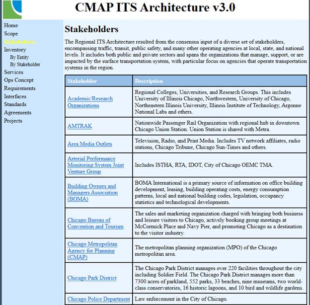
Figure 9. Stakeholder Output Example - Chicago
2.3.3 Regional Goals, Objectives, and Strategies
Connecting a region's planning processes to the ITS services in the architecture makes the architecture more useful to the region and more maintainable over time.
2.3.3.1 Definition
Transportation planning considers changes to be made to a region's transportation network in order to address regional needs. These needs are expressed by a set of goals, objectives or strategies. A goal is a broad statement that describes a desired end state. In the metropolitan or statewide transportation planning process, goals stem from the values inherent in the area's vision [1](e.g. Increase the safety of the transportation system for motorized and non-motorized users). Objectives are specific, measurable statements related to the attainment of goals[2]. Strategies are approaches that a region may take to address the goals or objectives.
2.3.3.2 Summary
|
POLICY
|
23CFR940.9 and FTA National ITS Architecture Policy Section 9 indicates that "A regional ITS architecture shall be developed to guide the development of ITS projects and programs and be consistent with ITS strategies and projects contained in applicable transportation plans". Making the connection between Strategies and the Regional ITS Architecture addresses this requirement and provides a way to link the architecture to the planning process.
|
|
Approach Key Activities
|
Identify key Planning Documents - Long-range planning - Planning for Operations - Transportation Systems Management and Operations (TSMO)
Engage Stakeholders to define which planning attributes to consider - Gain consensus on which attributes to consider
Connect planning terms to the architecture (e.g. to the Service Packages) - Use RAD-IT to document connection - ARC-IT provides suggested connections
|
|
INPUT Sources of Information |
- Metropolitan Transportation Plan - ITS Strategic Plan - Regional TSMO Plan
|
|
OUTPUT Results of Process |
- Connection of regional planning goals/objectives to ITS services in the architecture
|
2.3.3.3 Relationship to Other Components
As shown in the figure below (which uses the shorthand-Planning Objectives / Strategies), Regional Goals, Objectives, and Strategies can be related to Services and user needs in the Regional ITS Architecture. In addition, when projects are defined, the projects can be related to the objectives and strategies through the services defined for the project.
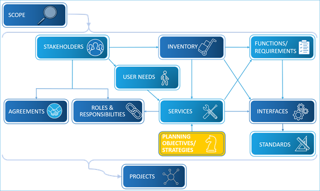
Figure 10. Regional ITS Architecture Components – Planning
2.3.3.4 Approach
When updating a Regional ITS Architecture it is important to consider how stakeholders will use the resultant update. Use of the architecture falls into two general areas: Use for Transportation Planning and Use for Project Development. In order to make the connection to transportation planning, an architecture update effort should connect the Services (and/or projects) of the architecture to the relevant aspects of planning. There are several aspects of planning that could be considered including:
- Long-range planning
- Planning for Operations
- Transportation Systems Management and Operations (TSMO)
The basic activities in the development or update are described below:
1. Identify Key Planning Documents.
Identify which planning documents to consider in making the connection between the architecture and planning attributes.
2. Engage Stakeholders to define which planning attributes to consider.
Each update process includes interaction with a set of key stakeholders, some of whom are from the planning disciplines. A suggested approach is to engage them in a discussion of which planning attributes to consider when making the connection to the architecture. Since they may be the users of the architecture in the planning community, making a connection that is relevant or resonates with these stakeholders is essential. Decide upon the two levels of attributes which will be supported in RAD-IT (see discussion on the RAD-IT tab) and gain consensus with the planning stakeholders on the choice.
3. Make connection from Planning Attributes to the architecture (e.g. to the Service Packages)
The next step is to map those planning attributes to service packages of the architecture. The ARC-IT website has a set of connections between planning attributes and service packages that can be used as a basis for the mapping. Providing this mapping as part of the architecture provides a real connection between the architecture and planning. In addition to service packages, the planning attributes can be connected it Projects in RAD-IT providing an additional connection point between planning and the architecture.
You are really looking for operations planning documents for the region.
If a focused operations planning document like a TSMO is available, consider
using the outputs of these efforts to make a connection to the architecture
through the defined strategies, some, but not all of which, will have a
technology component. If there is not a TSMO, then you will typically be
parsing a broader long range plan for operations and technology related goals,
objectives, and strategies. It is also important to cite your references and
include a link to the actual documents used if available.
2.3.3.5 RAD-IT
The key information connecting planning to the architecture can be found on the RAD-IT Planning tab, which is shown below for the sample database.

Figure 11. Planning Tab in RAD-IT
RAD-IT allows two levels of planning terms to be connected to the architecture. The default hierarchy is "Objective" and "Strategy", as shown in the example, but these terms are customizable. The two levels of planning attributes could be defined as "Goals" and "Objectives", "Objectives" and "Strategies", or "Needs" and "Actions", or any other pair of attributes. RAD-IT allows you to name the statements so they match the terminology used in the regional plan(s).
RAD-IT allows any two levels to be used, depending on what a particular region is using for its various planning document. For each statement, you can define the source document, the statement itself, any additional descriptive material available for the statement, and the service packages that map to the particular statement. In addition, RAD-IT allows the mapping of performance measures and projects to each planning statement.
2.3.3.6 Examples
The connection to Planning contained in RAD-IT can be added to an architecture website. The examples below show two different ways to represent this information.
This example shows the mapping of service packages to one objective. This is an example of a website generated directly from the RAD-IT file.

Figure 12. RAD-IT Planning Example - Memphis
This next example shows a portion of the mapping of Goals and Actions to both service packages and projects. This is an example of a custom designed website generated using information from a RAD-IT file.

Figure 13. RAD-IT Planning Example - New York City
2.3.4 Inventory of Elements
Each stakeholder agency, company, or group owns, operates, or maintains ITS systems in the region. In this step, a comprehensive inventory of these existing and planned systems is developed based on existing information and stakeholder input.
2.3.4.1 Definition
ITS Elements are the systems, devices, or equipment, that provide ITS services or share information as part of the ITS services. An inventory also includes non-ITS elements that provide information to or get information from the ITS elements. An comprehensive inventory of "ITS elements" is one of the key building blocks for a regional ITS architecture that represent these systems.
2.3.4.2 Summary
|
POLICY |
An inventory of existing and planned ITS elements supports development of requirements and information exchanges with these ITS elements as required in 23CFR940.9(d)6 and FTA National ITS Architecture Policy Section 5.d.6.
|
|
APPROACH Key Activities
|
If updating an existing regional ITS architecture: - Review the existing inventory o Use latest planning documents and interview key stakeholders - Revise the inventory o Check RAD-IT inventory for completeness and consistency o Input revisions into RAD-IT - Review inventory updates with stakeholders
If defining a new regional ITS architecture: - Collect existing information o Locate inventory data already be documented in Regional ITS Plans, e.g., EDPs, ITS studies, ITS Project documentation, Requests for Proposals (RFPs), etc. - Create initial inventory o Use collected inventory data to create an initial inventory o Define stakeholder, status, a brief description, and its mapping to ARC-IT physical objects - Review with stakeholders o Review the initial inventory with key stakeholders o Facilitate a broad review and incorporate comments
|
|
INPUT Sources of Information |
- Stakeholders - ITS Plans and Studies (Various) - TIP, STIP, Long Range Transportation Plan, etc.
|
|
OUTPUT
|
- Inventory of existing and planned ITS systems in the region
|
2.3.4.3 Relationship to Other Components
As shown in the figure below, inventories are mapped to many components of the Regional ITS Architecture. Each element in an inventory includes a name, associated stakeholder(s), a concise description, general status, and the associated physical objects (subsystems or terminators) from ARC-IT. Mapping to ARC-IT allows ITS services, functional requirements, potential interfaces and associated standards, etc. to be identified from the ARC-IT for the element.

Figure 14. Regional ITS Architecture Components – Inventory
2.3.4.4 Approach
Whether this is an update to an existing architecture or the development of a completely new architecture the approach for the architecture's inventory involves ensuring the right system elements are identified and mapped to the correct ARC-IT physical objects.
The next sections describe the different activities involved in each approach:
- Developing an Initial Inventory
2.3.4.4.1 Updating an Existing Inventory of ITS Elements
For an Architecture Update, the inventory already exists and it is a matter of reviewing, updating, and possibly adding new elements. The basic activities in updating stakeholders are given below.
2.3.4.4.1.1 Review the Existing Inventory
The approach to updating an inventory of ITS elements starts with reviewing the existing inventory information and considering whether the inventory of ITS element in the region has changed since the previous version of the architecture. In addition, existing plans, studies, project documentation, and adjacent or overlapping regional ITS architectures are a good source to use for updating inventory information. A portion of the inventory in adjacent architectures will often be relevant, saving time and improving consistency between adjacent or overlapping architectures.
The ITS Elements inventory covers the geographic, timeframe and services scope specified for the region. Ideally, the previous geographic scope of a region was established so that it represents many existing and planned systems that may be implemented over the timeframe of the architecture, can be developed in a single pass or in multiple passes. For example, an update might start with updating the existing inventory of existing ITS elements, then updating planned elements (i.e., elements that have been programmed), and finally add future elements that may be implemented towards the end of the established timeframe.
Each element in an inventory normally includes a name, associated stakeholder(s), a concise description, general status, and the associated subsystems or terminators from the ARC-IT. A more detailed discussion of these parts of the element definition is given below in the Developing an Inventory of ITS Elements section.
2.3.4.4.1.2 Revise the Inventory
For almost all regional ITS architectures the actual revision of the Inventory of ITS Elements will be done in the RAD-IT Inventory Tab (see discussion on RAD-IT Tab). In addition to including the updates defined in the previous step, the previous version of the Inventory should be checked for completeness and consistency. To begin it is helpful to create a table of Elements sorted by Stakeholder from the previous version. This table will highlight issues such as elements that do not have descriptions, elements that do not have stakeholders assigned, or elements with incorrect status fields.
Use RAD-IT to generate an "Unconnected Elements" table from the Check Your Architecture menu to highlight any elements that are not currently used in any service packages or connected to any other elements.
Another item to consider is whether the Inventory needs to be expanded or compressed. Both the number of stakeholders and the level of detail used in element definition will impact the size of the Inventory. A more detailed description of some of the tradeoffs related to Inventory is contained below in the Developing a New Inventory of ITS Elements section.
Review the list of new stakeholders identified since the last update and interview them to see what ITS elements they have or plan to have in the future.
2.3.4.4.1.3 Review Inventory Updates with Stakeholders
Working closely with the stakeholders as the inventory is updated and refined improves the quality of the inventory and increases stakeholder awareness of the existing and planned transportation systems in the region. Once the inventory has been revised a detailed review with the stakeholders either in workshops, or through web review should be held in order to get consensus on the Inventory update.
 A recommendation is that agencies of similar nature are described in a
consistent manner. For example, the various municipalities might each be named
"City of xxx", while the counties might be named yyy County. This is important
because element information is usually sorted alphabetically, so a consistent
naming convention allows the stakeholders to more easily see their information.
A recommendation is that agencies of similar nature are described in a
consistent manner. For example, the various municipalities might each be named
"City of xxx", while the counties might be named yyy County. This is important
because element information is usually sorted alphabetically, so a consistent
naming convention allows the stakeholders to more easily see their information.
2.3.4.4.2 Developing a New Inventory of ITS Elements
A regional ITS architecture inventory is a list of all existing and planned ITS elements in a region as well as non-ITS elements that provide information to or get information from the ITS elements. The focus should be on those elements that support, or may support, interfaces that cross stakeholder boundaries (e.g., inter-agency interfaces, public/private interfaces). Each element in an inventory will normally include a name, associated stakeholder(s), a concise description, general status, and the associated physical objects (subsystems or terminators) from ARC-IT. This core information may be supplemented with specific location information, points of contact, other references, and various implementation details as needs dictate. The region should establish the information that is required for each inventory element based on the needs of the region and available resources.
The fields that are normally included for each inventory element are:
- Element Name: Each element name should be selected with several criteria in mind. Most importantly, the selected name should be easily recognizable by the stakeholders. Preferably, the name will be the "common usage" name for the element in question, or at least be in terms that are familiar to the stakeholders.
- Associated Stakeholders: While stakeholders can participate in the consensus of any part of the regional ITS architecture, they often are most interested in the inventory elements that they own, operate, or maintain. Documenting the association between stakeholders and ITS elements is useful since it allows stakeholders to rapidly identify their own elements. This association helps individual stakeholders make the most effective use of their time. If individual stakeholders don't have time to review the entire regional ITS architecture, they might still be able to review all sections that involve their associated agency, company or interest group, as identified by the associated stakeholder.
- Element Description: While it may be tempting to include very detailed information in the element description when it is available (e.g., the numbers and types of controllers included in a particular ITS element), remember that this level of detail will increase the level of effort required to maintain the regional ITS architecture later. In general, the architecture inventory should not specify technologies or manufacturers since this information is subject to change and incidental to the purpose of the regional ITS architecture. Limit the information to what is required for the stakeholders to recognize the element and its role (i.e., "what does it do?") in the regional ITS architecture. Where a general element is used to represent many systems, the description could include an explicit list of these systems. Additional detailed information that is compiled can be archived separately for later use.
- Physical Object Assignments: Each regional ITS architecture inventory element should be mapped to one or more ARC-IT physical objects, i.e., subsystems and/or terminators. This association must be created because it will lead to identification supporting services, functional objects (and requirements) for the ITS element, and information flows and relevant ITS standards in later steps. Occasionally, an element will be truly unique and not represented in ARC-IT at all. In this case, no ARC-IT association is created. This is a perfectly valid approach, but it does mean that the functionality, information flows, and standards that are identified later for the element will not have a basis in ARC-IT. However, given the wide range of physical objects defined in ARC-IT, most elements can be mapped to an existing physical object.
2.3.4.4.2.1 Collect existing information
The process of creating an inventory of ITS elements starts with collecting existing inventory information. This can often provide an excellent jumpstart to the inventory definition. In addition to existing plans, studies, and project documentation, adjacent or overlapping regional ITS architectures are a good source for inventory information. A portion of the inventory in these architectures will often be relevant, saving time and improving consistency between adjacent or overlapping architectures. It is best to develop a partial inventory based on these resources prior to engaging a large number of stakeholders to make best use of stakeholder time.
 It is helpful to establish a naming convention before assembling
the inventory. For example, the names that are used in the inventory should
start with a standard prefix since the inventory will frequently be viewed and
managed as an alphabetized list of names. Prefixes can be a concise and
consistent reference to the stakeholder (e.g., XYZ Transit), a reference to the
location (City ABC), or any other standard prefix that will group similar ITS
elements when the inventory is sorted alphabetically by name. By establishing
and using a naming convention at the outset, the inventory will be easier to
read and manage, and there will be less rework later to rename and reorganize
the inventory after it is assembled.
It is helpful to establish a naming convention before assembling
the inventory. For example, the names that are used in the inventory should
start with a standard prefix since the inventory will frequently be viewed and
managed as an alphabetized list of names. Prefixes can be a concise and
consistent reference to the stakeholder (e.g., XYZ Transit), a reference to the
location (City ABC), or any other standard prefix that will group similar ITS
elements when the inventory is sorted alphabetically by name. By establishing
and using a naming convention at the outset, the inventory will be easier to
read and manage, and there will be less rework later to rename and reorganize
the inventory after it is assembled.
2.3.4.4.2.2 Create Initial Inventory
When building an inventory, focus first on the "centers" since they are typically involved in the majority of inter-agency and public/private interfaces that need the most attention. Focus next on the field, vehicle, and traveler ITS elements where there is some opportunity for integration. Next consider other ITS elements that are in the region that may interface with ITS. Airports, asset management systems, and special event centers are examples of ITS elements in the region that may provide integration opportunities and should be included in the inventory. Finally, consider centers in adjacent regions, like the TMC in the adjacent state. The objective is to identify the ITS elements in the region that will allow integration opportunities to be identified and considered later in the process. Unless the region has unique needs, don't include ITS elements in the inventory for people (e.g., traffic operations personnel). The focus should be on the systems in the region that may be integrated. Systems with no potential for integration (e.g., an isolated traffic signal in a remote community) need not be included in the inventory.
The inventory should cover the geographic, time horizon and services scope specified for the region. The inventory, representing many existing and planned systems that may be implemented over ten or twenty years, can be developed in a single pass or in multiple passes. For example, you might start with an inventory of existing ITS elements, then add planned elements (i.e., elements that have been programmed), and finally add future elements that may be implemented towards the end of the established timeframe.
The level of granularity in the inventory can vary based on the type of elements and also can vary within a single regional ITS architecture. For example, larger systems in a major metropolitan area may be explicitly identified (e.g., "District 8 Freeway Management Center"), but smaller systems may be represented more broadly with a few general ITS elements (e.g., "Municipal Police Dispatch Centers"). The approach of "rolling up" smaller systems into a general inventory element suggests that these systems should integrate with other regional elements in a consistent fashion. A detailed list of the agencies and systems represented by the general ITS element can be included in the definition for the element. A more detailed discussion of issues associated with granularity of inventory is given below.
An inventory may include a few ITS elements that are outside the defined scope of the region. For example, a Statewide ITS Architecture inventory may include ITS element(s) representing operations centers in adjacent states where there are important interfaces to these operations centers. These shared elements and "inter-regional" interfaces should be coordinated across regions to avoid duplicate and/or conflicting definitions of the same element or interface. The names of the ITS elements in both architectures must be identical when they represent the same system, and the interfaces defined in both regional ITS architectures should be identical when they describe the same information exchange across regional boundaries.
2.3.4.4.2.3 Review with Stakeholders
Working closely with the stakeholders as the inventory is expanded and refined improves the quality of the inventory and increases stakeholder awareness of the existing and planned transportation systems in the region. Many different mechanisms may be used to gather stakeholder input including workshops, smaller meetings, telephone surveys, e-mail, and web-based interactions. Plan to use one or more of these mechanisms to verify and improve the inventory with stakeholder feedback. It may be helpful to engage a few key stakeholders initially and then encourage a broader review once the inventory is substantially complete.
 In general, the inventory should be managed so that it is as small as
possible while still supporting the goal of identifying all key integration
opportunities in the region. For example, instead of identifying separate
inventory elements for each type of field equipment (e.g., separate elements for
variable message signs, signals, cameras, etc.), consider identifying a single
inventory element that includes all of the field equipment.
In general, the inventory should be managed so that it is as small as
possible while still supporting the goal of identifying all key integration
opportunities in the region. For example, instead of identifying separate
inventory elements for each type of field equipment (e.g., separate elements for
variable message signs, signals, cameras, etc.), consider identifying a single
inventory element that includes all of the field equipment.
Multiple ITS elements can be safely grouped into a single inventory element if they exchange the same types of information with the same elements, and if they will be deployed for the same function over time. (E.g. message signs for a freeway and message signs for transit traveler information at a bus stop probably should be identified as separate ITS elements because of the very different requirements for these ITS elements.) The grouping works in the figure below because all the Heartland field equipment interfaces exclusively with the Heartland TOC, and for example, might be part of a single freeway management system deployment project. If some of the field equipment was actually owned and operated by another agency, then it might be best to identify a separate ITS element for that equipment group.

Figure 15. Grouping ITS Elements into General Inventory Items
Another consideration is that when ITS elements are grouped in the inventory, the potential interfaces between these elements are lost (e.g., any potential interface between different types of Heartland field equipment is lost with the grouping in the figure above). Again, the grouping is acceptable because the interface between field equipment is (presumably) not a significant regional interface. The last issue is the affect that that grouping has on ITS standards identification later in the process. Due to the grouping, the combination of ITS standards that support Dynamic Message Signs (DMS), Closed Circuit Television (CCTV) Control, and Signal Control will all be associated with the interface to the combined Field Equipment Element. This means that the ITS standards information for the element must be interpreted and used carefully to ensure that device-specific standards are identified and used properly later in the process. As long as the ITS element grouping is done with these issues in mind, recent experience indicates that grouping will save regional ITS architecture development time with little or no impact to the quality and utility of the final architecture.
2.3.4.5 RAD-IT
The key information about the ITS elements can be found on the RAD-IT Inventory tab, where the names, descriptions, associated stakeholder, status and mapping to ARC-IT components are contained.

Figure 16. Inventory Tab in RAD-IT
The Inventory tab from RAD-IT is shown above and is the tab where the initial updates of inventories names, associated stakeholders, its descriptions, and associated subsystems/terminators are performed.
Based on the way RAD-IT works, any update to inventory information on the inventory Tab will automatically be available on the Functions and Interfaces tabs, which can then be updated as part of those component updates.
 RAD-IT can identify inconsistencies and potential errors in the architectures.
Consider running the "Inventory to Service Package Comparison report" which
compares Inventory and Service Package selections and identifies possible
Inventory and/or Service Package selection gaps. This report identifies ARC-IT
and user defined physical objects and inventory elements that are not assigned
to any Service Package, as well as elements that are not assigned to a Service
Package where it is possible to include them.
RAD-IT can identify inconsistencies and potential errors in the architectures.
Consider running the "Inventory to Service Package Comparison report" which
compares Inventory and Service Package selections and identifies possible
Inventory and/or Service Package selection gaps. This report identifies ARC-IT
and user defined physical objects and inventory elements that are not assigned
to any Service Package, as well as elements that are not assigned to a Service
Package where it is possible to include them.
2.3.4.6 Examples
The key ITS Elements inventory is usually described by a table or the Inventory page on the website. In both cases the information is provided alphabetically. Although inventories all tend to include approximately the same information, there are a variety of ways to document this information have. The first example below from the Bay Area Regional ITS Architecture has a web design that does not represent a RAD-IT web generation facility. The second example, from the Ohio Statewide ITS Architecture shows Elements by Stakeholder generated using the RAD-IT web generation facility.

Figure 17. Example of an Inventory Summary from the Bay Area Regional ITS Architecture

Figure 18. Example of an Inventory Table from the Ohio Statewide ITS Architecture
2.3.5 ITS Services
The services performed by ITS systems meet the stakeholders' needs for a region and demonstrate how the elements are connected.
2.3.5.1 Definition
ITS services are transportation services performed using ITS elements that are deployed to meet the region's operational goals and objectives. In a regional ITS architecture service packages are used to identify the pieces of the architecture that are required to implement a particular ITS service.
2.3.5.2 Summary
|
POLICY
|
An understanding of the ITS services supports development of requirements and information exchanges with planned and existing ITS elements as required in 23CFR940.9(d)6 and FTA National ITS Architecture Policy Section 5.d.6.
|
|
APPROACH Key Activities
|
If updating an existing regional ITS architecture: - Identify Service Package Changes - Update Service Packages o Revise stakeholders, elements, and status o Add new services as needed - Review Service Package Updates with Stakeholders
If defining a new regional ITS architecture: - Create initial list of ITS services o Review service priorities documented in plans, studies, etc. o Review regional goals or strategies and identify candidate services o Collect inputs about services from key stakeholders including operators, maintainers, and users of the transportation system - Create full set of ITS service packages o Assign elements to the services identified - Gather Stakeholder Inputs o Build consensus on services for the region via stakeholder meetings or online reviews o Focus discussions on those services that require group buy-in.
|
|
INPUT Sources of Information
|
- Stakeholders - Planning Studies (e.g., transportation plans, strategic ITS plans, etc.) - TIP, STIP, Congestion Management Plan, project documents, etc.
|
|
OUTPUT Results of Process |
- Documented regional needs and ITS service priorities - Documented association between ITS services and supporting systems
|
2.3.5.3 Relationship to Other Components
Service packages are made up of several other components of the regional ITS architecture. Every ITS service package selected for the region is associated with one or more inventory elements that support that service, functional objects, which relate to the functional requirements, for these elements, and information flows, which are defined for the interfaces. A set of user needs is defined for each service package in ARC-IT, which may be used to jumpstart the user needs that are included in the regional ITS architecture. The service packages in which a stakeholder participates support their Roles and Responsibilities. The Service Packages are also the way that Planning Objectives/ Strategies are addressed in a region.

Figure 19. Regional ITS Architecture Components - Services
2.3.5.4 Approach
Whether this is an update to an existing architecture or the development of a completely new architecture the approach for the architecture's services involves discussions with stakeholders regarding their current and future needs for transportation, identifying the appropriate ITS service that will meet those needs (sometimes expressed in the region's planning goals or objectives), and identifying the elements that will need to participate in each of those services.
The next sections describe the different activities involved in each approach:
2.3.5.4.1 Updating ITS Services
The approach to updating ITS services for a regional ITS architecture is, in essence, the approach taken to update the services packages as described in RAD-IT or in any diagrammatic material contained in the architecture. This is because, as noted above, service packages identify the pieces of the architecture that are required to implement a particular service. The key steps in almost any approach taken to updating service packages would include:
- Identify the changes to service packages from the previous update
- Put those changes into RAD-IT and update the outputs
- Review the changes with the stakeholders for concurrence
2.3.5.4.1.1 Identify Service Package Changes
The first source of changes to Service Packages will likely come from the definition of Goals, Objectives, and Strategies for the region. These planning concepts are an expression of the stakeholders' needs regarding transportation in the region. A subset of these planning needs can be addressed by ITS services.
Although RAD-IT (formerly Turbo Architecture) has supported making the connection between planning concepts and ITS services for over 5 years, it is only in the past couple years that regions have started defining this connection within the regional ITS architecture. If the previous version of the architecture contains this mapping, then the approach to updating this component is to review the current regional set of planning concepts (e.g. goals, objectives, and strategies) to identify service packages that can support them. Identify any gaps between the revised planning concepts and the set of service packages from the previous version. These gaps should be considered for each stakeholder. For example, a previous version of an architecture might have a service package implemented by a single stakeholder in the region, but this remains a potential "gap" for other stakeholders in the region.
Long range transportation plans typically discuss economic and social trends and how the infrastructure should be built to meet the region's needs. Many of these long-term policies and goals are directly related to the needs and services that guide a regional ITS architecture. For example, if major new facilities are planned for the region, then it is appropriate to plan to add ITS services into those new facilities. If the region is making major investments in enhancing transit service, these enhanced services should be reflected in the regional ITS architecture.
Some regional ITS architectures may have a mapping from Regional Needs (or some other formulation not directly tied to the planning documents) to ITS services. A recommendation is to change this mapping to a more explicit connection to the transportation planning concepts in order to facilitate use by transportation planners. Some of the regional needs used in these previous versions are related to the current User Needs component and can be used to help in the update of that component.
The second major source of Service Package update information is through interaction with the stakeholders. As mentioned in the overall approach to updating a regional ITS architecture, a key early step in the update is to talk to key stakeholders to understand what updates they envision to their ITS deployments. This usually takes the form of interviews with key stakeholders regarding the service packages which the architecture currently identifies they participate in and identifying any additions/ subtractions/ or modifications of services implemented or planned by the stakeholder.
A significant source of possible new service packages to consider can be found in the current version of ARC-IT. See www.arc-it.net.
One of the best sources for potential service package changes is the conversion table outputs that identify all service packages that have been added, removed, or modified since the architecture was last updated.
2.3.5.4.1.2 Update Service Packages
Updating service package information is the key next step after collecting changes from the stakeholders. Because any regional ITS architecture is too large to fit onto a small number of diagrams, the service packages represent a key way to break up architecture information in a way that is easily understood and used by the stakeholders.
A service package is composed of elements, functional objects (within the elements) and information flows between the elements. Every ITS service selected for the region should be associated with one or more inventory elements that supports or will support that service. As part of the update you may want to run a report in RAD-IT called the Inventory to Service Package Comparison report that will identify potential inventory or service package gaps.
As shown below on the RAD-IT tab discussion, the Services tab contains the service package name, status, and mapping to elements of the architecture. Other aspects of the service package are entered on the Functions and Interfaces tabs. Diagrammatic outputs of service packages, whether coming directly from RAD-IT or from another diagrammatic tool (see below for examples of both) would be created as part of the update so that the revised diagrams could be reviewed with the stakeholders.
2.3.5.4.1.3 Review Service Package Updates with Stakeholders
The updates to service packages will be a key element of any review with stakeholders carried out as part of the update. In this review, organizing the information via a website or diagrams is a key to gaining consensus with the stakeholders on the changes. If done via stakeholder meetings, a suggestion is to use focused engagements so that stakeholders' time will be spent focusing on their portions of the architecture. This can be done by breaking into groups organized by stakeholder areas (e.g. traffic, transit, or public safety)
 A suggestion is to use the Service Package Instance feature of RAD-IT to
create a set of service package instances for each service that focus on the
important interfaces centering on a single stakeholder. For example, if your
architecture has the service package TM03 Traffic Signal Control (and pretty
much every architecture does have this one), create a separate TM03 instance
for each city, county, or state stakeholder actively engaged (or planning to be
engaged) in traffic signal control. Putting the stakeholder name in the service
package instance title will make it easy for stakeholders to identify service
packages that focus on their operations. Using these instances will allow
creation of simpler service package diagrams (either using the RAD-IT output or
web features or using a customized diagram capability).
A suggestion is to use the Service Package Instance feature of RAD-IT to
create a set of service package instances for each service that focus on the
important interfaces centering on a single stakeholder. For example, if your
architecture has the service package TM03 Traffic Signal Control (and pretty
much every architecture does have this one), create a separate TM03 instance
for each city, county, or state stakeholder actively engaged (or planning to be
engaged) in traffic signal control. Putting the stakeholder name in the service
package instance title will make it easy for stakeholders to identify service
packages that focus on their operations. Using these instances will allow
creation of simpler service package diagrams (either using the RAD-IT output or
web features or using a customized diagram capability).
2.3.5.4.2 Defining ITS Services
The steps below describe an approach for defining ITS services in an architecture for the first time.
2.3.5.4.2.1 Create Initial List of ITS Services
The first step in creating a set of ITS services for a region is to review the planning documents for the region, which are described under the Regional Goals, Objectives, and Strategies component. Transportation long range plans typically discuss economic and social trends and how the infrastructure should be built to meet the region's needs. Many of these long term policies and goals are directly related to the ITS services that guide a regional ITS architecture. For example, if major new facilities are planned for the region, then it is appropriate to plan to add ITS services into those new facilities. If the region is making major investments in enhancing transit service, these enhanced services should be reflected in the regional ITS architecture.
The next step in developing an initial list of services is to review the Service Packages of ARC-IT. See www.arc-it.net. These service packages represent a very broad range of ITS services and identify the pieces of the architecture that are required to implement a particular service. They are also the key way that ITS services are described in RAD-IT (see the RAD-IT Tab). The developers can create an initial list of potential services and review these services with the stakeholders to gather their inputs. While the list of service packages in ARC-IT is quite extensive, there may be ITS services that go beyond those described in ARC-IT, or are variations of those in ARC-IT. Some regions have added services such as red light enforcement or flood monitoring, permitting coordination to the services identified by ARC-IT.
Beginning with a list of service packages or an alternative list of ITS services, services should be identified that:
- Are currently provided by the ITS elements in the region,
- Will be provided once planned projects are implemented, or
- Address regional needs and may be implemented in the future.
2.3.5.4.2.2 Create a Full Set of ITS Service Packages
Starting with the list of service packages, the next step is to identify the key components of each service package. These components are:
- Stakeholders
- Elements
- Information flows
These components should be entered into RAD-IT to fully define the architectures ITS services.
At this point, assuming Stakeholders and Elements have been defined you can focus on identifying the elements for each service. The stakeholder mapping will come because the elements are already mapped to a stakeholder. The information flows will be selected and customized during the Interfaces step.
2.3.5.4.2.3 Gather Stakeholder Inputs
Stakeholder input on each of these choices should be actively solicited, preferably in a direct forum like a brainstorming session or workshop. Remember that the focus for this task is on identifying the important ITS services; avoid getting bogged down in the specifics of how those services will be provided in this process step.
To make best use of stakeholder representative time, focus group discussion on ITS services that require group buy-in. ITS services that can be or will be implemented by a single agency require less discussion than ITS services that require integration between different stakeholders' ITS elements. For example, the decision to deploy a Surface Street Control service is an individual decision for a particular traffic agency, and may not be a priority for group discussion. In contrast, the decision to deploy Transit Signal Priority requires consensus by traffic and transit agencies and should be agreed to by all parties. Individual agency service choices can be coordinated offline if time is short.
It is usually appropriate to focus the discussion on services that have public sector involvement. Service packages that are exclusively private sector with no public sector interfaces (e.g., some autonomous vehicle safety and commercial services) can generally be excluded.
2.3.5.5 RAD-IT
The key information about Service Packages is contained on the Services Tab of RAD-IT. As shown below this is where the initial entry or updates of services names or descriptions and element mappings are performed. As shown on the tab, each service package has a name and description. In addition, the tab includes the indication of the status of the service (existing, planned, etc.), a list of projects associated with the service, and a listing of what elements are a part of the service. This last connection, between service package and elements is key to defining the interfaces contained in the service packages, as well as the functions defined for the elements.

Figure 20. Services Tab in RAD-IT
Once the interfaces tab has been filled out it is possible in RAD-IT to create service package diagrams such as the one below, which is for a service package instance of TM01 Infrastructure Based Surveillance from the above RAD-IT file.

Figure 21. Service Package Based Diagram Example
2.3.5.6 Examples
Examples of ITS Services can be found in every regional ITS architecture. The most common representation is found on architecture websites. There are many versions of architecture websites which can display services information in a variety of ways. Many regions create a website using RAD-IT to generate web pages. An example of how service packages are described on these sites is given in the example from the Nevada Statewide ITS Architecture shown below. In this case for each service package (instance) there is the name, description, list of elements in the service package, and a link to a diagram generated by RAD-IT. For this example, the diagram for this service package is shown below as well.

Figure 22. Nevada Service Package Web Page Example

Figure 23. Nevada Service Package Web Page Diagram
The second example comes from the Maricopa County Regional ITS Architecture, showing a diagrammatic view of the service package in addition to elements and information flows associated with the service package.
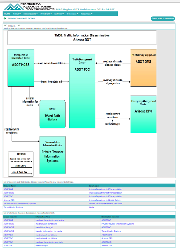
Figure 24. Maricopa County Service Package Example
2.3.6 User Needs
In a regional ITS architecture User Needs provide a starting point to determine system requirements that the ITS elements will need to satisfy in order to implement the ITS services.
2.3.6.1 Definition
A user need is a capability that is identified to accomplish a specific goal or solve a problem that is to be supported by the system. ARC-IT defines a set of user needs for all users that participate in ITS. These needs are apportioned to service packages according to the ability of those service packages to address these needs. User needs are then traced to requirements that are written for each functional object.
2.3.6.2 Summary
|
Policy |
User Needs are the used to derive system functional requirements which are a required component of the regional ITS architecture as identified in 23CFR940.9(d)5 and FTA National ITS Architecture Policy Section 5.d.5.
|
|
Approach Key Activities |
If updating an existing regional ITS architecture: - Review service package changes since the last update - Select user needs for each of the service packages in the region - Update tailoring of the needs if stakeholder organization names have changed or other changes to the default needs
If defining a new regional ITS architecture: - Select the user needs based on the service packages - Review the selected needs for consistency and accuracy - Customize or tailor the needs to reflect stakeholders and their priorities - Review with needs with stakeholders and update as needed
|
|
INPUT Sources of Information |
- Service Packages - Stakeholder(s) current system capabilities - Stakeholder(s) planned system capabilities and deployment needs
|
|
OUTPUT Results of Process
|
- A set of user needs based on the regional ITS architecture service packages
|
2.3.6.3 Relationship to Other Components
As shown in the figure below, user needs are mapped to several other components of the Regional ITS Architecture.

Figure 25. Regional ITS Architecture Components – Needs
The connection from Stakeholder to User Needs is an indirect though important connection. Users as represented by the set of stakeholders have needs that they expect to be met through their deployed ITS projects. These stakeholders' needs are reflected in the reviewed set of ITS elements and service packages. Once the service packages have been customized, reviewed, and updated to the satisfaction of the stakeholders then Needs become the starting point for tracing the requirements that are necessary to implement those systems.
2.3.6.4 Approach
The definition of User Needs relating to ITS Services were added in Version 8 of ARC-IT, so for most regional ITS architecture updates these will not have been previously defined.
The next sections describe the different activities involved in each approach:
- Updating Existing User Needs
- Defining a New Set of User Needs
2.3.6.4.1 Updating Existing User Needs
Some older architectures may have mappings to Regional Needs (or possibly even User Needs), which were usually related to the Planning attributes of regional objectives or strategies (see the Goals, Objectives, and Strategies section). These older references usually were not directly connected to transportation planning documents. The recommendation now is to try to make connections to the transportation planning documents. Use the Planning tab in RAD-IT to update the mapping between the Goals/Objectives to selected Service Packages in your regional architecture. Another approach is to update the needs using the User Needs drafted for ARC-IT for each service package.
 RAD-IT includes the ability to automatically add User Needs to an
architecture based on the service packages defined for the architecture (See RAD-IT Tab section below). A suggested approach
is to perform the service package updates as part of the update effort and then
create (or update if they did exist) the user needs for each service package
(or service package instance if the architecture includes these).
RAD-IT includes the ability to automatically add User Needs to an
architecture based on the service packages defined for the architecture (See RAD-IT Tab section below). A suggested approach
is to perform the service package updates as part of the update effort and then
create (or update if they did exist) the user needs for each service package
(or service package instance if the architecture includes these).
2.3.6.4.2 Defining a New Set of User Needs
For a regional architecture that did not have a set of user needs defined before or for a new regional architecture the best place to start is with the services that are defined and selected for the region. Using the service packages in ARC-IT there is a list of user needs written generically for each service package. Start with these and customize them for your region's stakeholders. What is it that the owners and operators of ITS need to improve their operations? What are their needs in terms of infrastructure and systems integration? Those can all be captured using the service packages as a starting point. Review the draft set of needs with the core group of stakeholders as the services, needs, and roles and responsibilities have been drafted. Update the needs in order to be ready to select the appropriate requirements in the subsequent steps.
Consider adding User Needs for projects defined in RAD-IT as this will
make the service package-based user needs available for use in project
development, including using SET-IT to develop more detailed project ITS
architectures and to support development of project concept of operations
(which will include the user needs).
2.3.6.5 RAD-IT
The key information about User Needs can be found on the RAD-IT User Needs tab, where the needs are shown for each service package (or service package instance).

Figure 26. Needs Tab in RAD-IT
In RAD-IT, Autoselect can be used to add the needs for all service packages, or if you are just updating needs, then Autoselect will add needs only for those service packages (or service package instances) added since the last update. Note: Autoselect will also delete user needs for service packages that are deleted from the architecture as part of the update.
2.3.6.6 Examples
The list or User Needs, organized by Service Package, can be added to an architecture website. The following example is a partial list of User Needs taken from the Memphis Urban Area Regional ITS Architecture website.
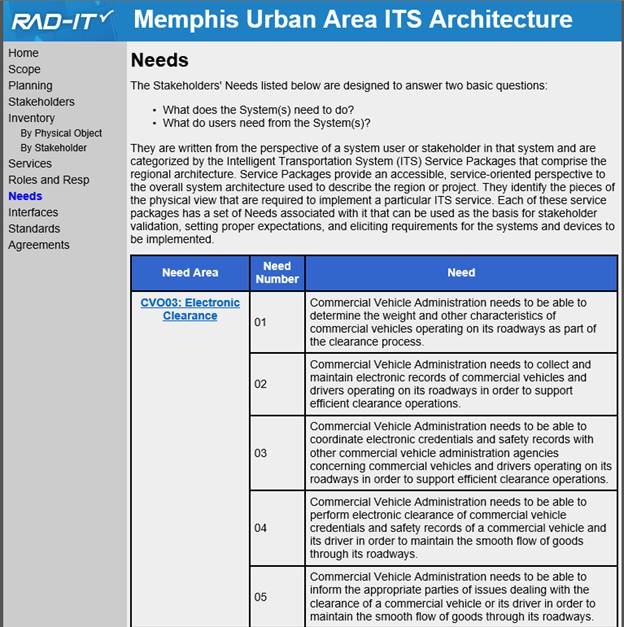
Figure 27. Example Needs for the Memphis Regional ITS Architecture
2.3.7 Roles and Responsibilities
Stakeholder roles and responsibilities (R&Rs) are defined as part of the regional ITS architecture.
2.3.7.1 Definition
Typically in transportation stakeholders own, develop, operate, or maintain portions of the transportation system. Responsibilities cover activities that the stakeholders engage in as they perform their roles. For example, an agency that operates traffic signal systems will be responsible for providing adequately trained staff, maintenance of the system, and provision of information about the system to other agencies and the public.
2.3.7.2 Summary
|
POLICY |
An operational concept that identifies the roles and responsibilities of participating agencies and stakeholders in the operation and implementation of the systems included in the regional ITS architecture is required in 23CFR940.9(d)3 and FTA National ITS Architecture Policy Section 5.d.3.
|
|
Approach Key Activities
|
If updating an existing regional ITS architecture: - Gather data on revisions of existing Roles and Responsibilities - Update Architecture's R&Rs and enter into RAD-IT R&R Tab - Review with Stakeholders, In person or on-line
If defining a new regional ITS architecture: - Gather data from existing documents, e.g., Incident Management Plans - Develop Roles/Responsibilities or Operational Concept o Build the list of stakeholders based on the elements and services o Identify roles and responsibilities in general service package areas (e.g. traffic management, public transport, etc.) o Draft an operational concept - Develop several relevant operational scenarios - Walk through scenarios and identify roles and opportunities for enhanced cooperation - Document each stakeholder's current and future responsibilities in each scenario - Collect key findings into a high level Operational Concept o Build Consensus - Review drafts with stakeholders and revise as needed
|
|
INPUT Sources of Information |
- Existing Roles and Responsibility information - Inventory, Needs and Services - Any documents that identify roles and responsibilities
|
|
OUTPUT Results of Process
|
- Operational Concept documentation for the region, including how ITS services are provided and the stakeholders' roles and responsibilities
|
2.3.7.3 Relationship to Other Components
The inventory identifies the stakeholders that are associated with each system in the region and the service packages identify the services that those systems will provide. Here, each stakeholder's current and future roles and responsibilities (R&Rs) are defined in more detail.
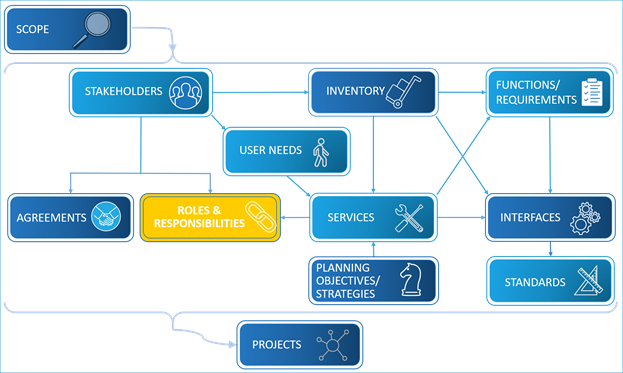
Figure 28. Regional ITS Architecture Components – Roles & Responsibilities
Roles and Responsibilities are directly assigned to stakeholders. The second connection shown in the figure is with Services because stakeholder's participation in services implies responsibilities the stakeholders have.
2.3.7.4 Approach
Depending on whether this is an update to an existing architecture or the development of a new regional architecture there may be different steps to consider for the operational concept of a region.
2.3.7.4.1 Updating Roles and Responsibilities
Regional ITS architectures all have some version of roles and responsibilities. The descriptions of them may be in RAD-IT, but they might also be in an architecture document. The basic approach to updating follows that of the overall update approach: identify changes, incorporate them into the architecture and review with stakeholders.
2.3.7.4.1.1 Identify Changes
The approach to updating the roles and responsibilities is to review the current version of the roles and responsibilities with the stakeholders and get their inputs on changes. Because the range of service packages will likely expand in architecture updates, the new responsibilities implied by the new service packages should be considered in the update. This review could be done via interviews, or as part of stakeholder meetings.
2.3.7.4.1.2 Incorporate Changes into Architecture
Once the changes have been collected, they need to be entered into the
architectures. Use RAD-IT to enter roles and responsibilities as shown below to
allow the information to be accessible to stakeholders on any websites that are
created for the architecture or as documentation is updated. In most cases the
roles and responsibilities will be defined by service package area, which is
the way that RAD-IT organizes them. If the description is in a document rather
than RAD-IT, then other organizations of the information (e.g. by stakeholder)
may be the starting point for the update. In some cases a region may have
created a more complete operational concept organized around some of the
service package areas which will also need to be updated.
See the discussion below under Developing Roles and Responsibilities regarding an operational concept.
If the range of services performed by the architecture is expanding (e.g. if connected vehicle services are being added), then the roles and responsibilities will likely need to be expanded to cover the new services. This expanded set should then be reviewed with the stakeholders.
2.3.7.4.1.3 Review with Stakeholders
The updated version of roles and responsibilities should be reviewed with the stakeholders either in meetings or by requesting review of the architecture website or architecture document. Based on stakeholder comments the roles and responsibilities would be revised to provide the final update.
Roles and responsibilities represent a high-level view of the services
provided by a stakeholder. As part of the update it is a good idea to reconcile
inputs from the stakeholders on roles and responsibilities with the service
packages in which the stakeholders participate. This will provide a good early
validation that your architecture is on the right track.
2.3.7.4.2 Developing Roles & Responsibilities
When developing a new regional ITS architecture the development of roles and responsibilities is the step where integration opportunities in the region are first documented, with particular focus on stakeholder involvement. The objective is not to formally define each ITS element or specify detailed integration requirements. This will come in later steps. The objective in this step is to identify current and future organizational roles in the regional transportation system. As with the other regional ITS architecture products, exactly how the roles and responsibilities information is gathered and expressed will vary from region to region. The most common approach to developing roles and responsibilities is to organize them around service package areas such as traffic management, transit management, or incident management.
Start by gathering data from existing regional documents such as a TSM&O operational strategy or regional incident management plans. These will contain information about each of the major stakeholders and their roles in critical operations.
Next, start building the list of roles and responsibilities for the key stakeholders. Use the information from the Inventory of elements and the Services discussed in previous sections to come up with the list of stakeholders to focus on.
Some regions may develop only a set of roles and responsibilities, but some may choose to go further towards developing an Operational Concept, which could augment the roles and responsibilities to include a more detailed discussion of how stakeholders will interact to provide specific transportation services, possibly in specific scenarios.
Perhaps the most critical factor in the success of the roles and responsibilities step is stakeholder involvement. The ultimate objective is not just to create a table of roles and responsibilities, but to have the stakeholders suggest, review and tangibly buy in to these decisions so that they are owners of the roles and responsibilities. When a region chooses to go beyond this level of information to a full Operational Concept, they often define the operational concept around role and responsibility areas, selecting one or two service packages as representative of these areas and describing scenarios relating to these services. For example, "Traffic Incident Management" and "Regional Traffic Control" both require broad inter-agency coordination and make excellent examples for regional operational scenarios.
 The National ITS Reference Architecture, ARC-IT, includes Service
Packages which can be used as a basis for operational concept development.
Basic service package information is readily accessible on the ARC-IT website. Click "Architecture" and
"Service Packages" from the pull-down menu to see a diagram, a tab of
enterprise information, planning goals/objectives, needs/requirements, source
information, security considerations, and standards that apply to the objects
in this service. These pages provide a good resource for those developing
operational concepts for the region.
The National ITS Reference Architecture, ARC-IT, includes Service
Packages which can be used as a basis for operational concept development.
Basic service package information is readily accessible on the ARC-IT website. Click "Architecture" and
"Service Packages" from the pull-down menu to see a diagram, a tab of
enterprise information, planning goals/objectives, needs/requirements, source
information, security considerations, and standards that apply to the objects
in this service. These pages provide a good resource for those developing
operational concepts for the region.
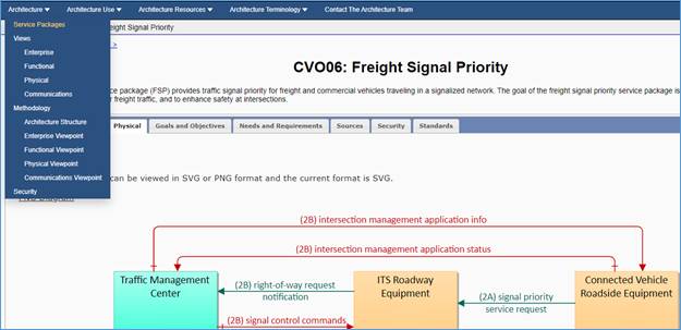
Figure 29. ARC-IT Service Package Page
Another approach used by some regions is to use real operational situations, or scenarios, to guide the discussion. For example, a large winter storm or hazardous material spill can provide vivid context to a discussion of the roles and responsibilities of stakeholders in the region. Create a scenario or scenarios that the stakeholders in the region are vitally interested in and then use the scenarios to encourage discussion and make the operational concept documentation more accessible.
One way to use a scenario-based approach is to organize a meeting where a facilitator walks key stakeholders through the events of a prepared scenario. At each step in the scenario, the facilitator works with the group to determine:
1. Current roles and responsibilities. For example, the state DOT currently faxes daily lane closure information to the counties, the major metropolitan city in the region, and the media.
2. What are the problems? For example, lane closure information tends to be very dynamic. Many agencies that could use the data don't receive it (e.g., emergency medical services).
3. What are the opportunities? For example, enhance coordination of longer-term closures between agencies. Collect closure information for the region in one place and make this available to all operating agencies as well as the traveling public.
The facilitator should be prepared for more "opportunities" to be identified than can be thoroughly addressed in real-time. A common approach is to list all the ideas and then prioritize a few to flesh out with an operational concept.
When it comes to the implementation and maintenance of complex regional
systems the lines of responsibility can get more complicated. One idea is to
develop a responsibility matrix with the shared resources on one axis and the
stakeholders on the other. Let the stakeholders populate each cell with their
responsibilities for the shared resource.
 Security Considerations
From a security perspective, there are roles and responsibilities associated with making sure the security objectives are met. While you have your stakeholders thinking about their roles and responsibilities for ITS it can also be a good time to establish their R&Rs with respect to security as part of the operational concept. Leverage expertise from organizations in the region that have specific interest and expertise in information security.
2.3.7.5 RAD-IT
The key information about Roles and Responsibilities can be found on the RAD-IT R&R tab, where the roles and responsibilities are organized by Roles and Responsibility Areas. These areas usually represent service package areas (as defined in ARC-IT), however regions can choose to create their own areas if desired.

Figure 30. R&R Tab in RAD-IT
Within a single role and responsibility area, selecting one of the stakeholders provides a list of the actual roles and responsibilities, which can be edited as needed (see the figure below).

Figure 31. R&R Tab in RAD-IT Details
2.3.7.6 Examples
There are several examples below of Roles and Responsibilities from existing regional ITS architectures. In all of these cases the component is defined as Operational Concept, which contains the roles and responsibilities. In some cases these are shown in documents. The example below is the first page from the Operational Concept from the Alabama Statewide ITS Architecture.
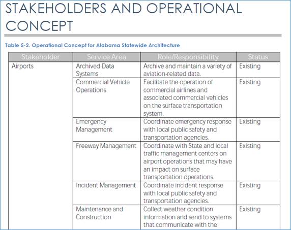
Figure 32. Alabama Statewide Architecture Operational Concept Example
Roles and Responsibilities can be described on websites in a variety of ways. The diagram below shows one example from the Hawaii Statewide ITS Architecture, which is organized by stakeholder, with the example below showing a portion of the R&R for the Hawaii DOT – Highways Division.
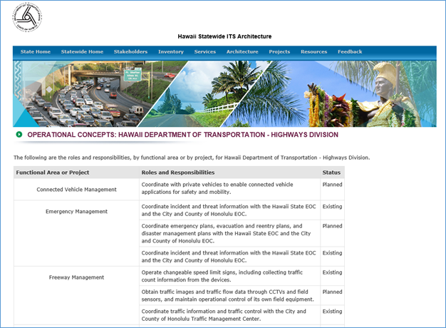
Figure 33. Hawaii Statewide Architecture Operational Concept Example
Another example of Roles and Responsibilities on a web version of an architecture is the one shown below from the San Francisco Bay Area ITS Architecture. This architecture shows an Operational Concept organized by Service Package area with the example showing a portion of the Traveler Information section of the Operational Concept.

Figure 34. Bay Area ITS Architecture Operational Concept Example
2.3.8 Functions and Requirements
A regional ITS architecture includes an identification of the functions and functional requirements for the major ITS elements in the region.
2.3.8.1 Definition
Functional requirements are a high-level description of the required functionality for each ITS element to provide the ITS services that have been identified for the region. They describe WHAT a system must do to provide the ITS services. In a regional ITS architecture, the functional requirements focus on the high-level requirements that support regional integration. For a project ITS architecture, these are broken down into more detailed requirements to document fully the functionality of the system.
2.3.8.2 Summary
|
POLICY
|
Identification of system functional requirements is a required component of the regional ITS architecture as identified in 23CFR940.9(d)5 and FTA National ITS Architecture Policy Section 5.d.5.
|
|
APPROACH Key Activities
|
If updating an existing regional ITS architecture: - Revise functional objects mapped to elements once Inventory is updated then revise requirements as needed
If defining a new regional ITS architecture: - Identify the ITS elements that require functional requirements definition. Systems on the boundary of ITS (e.g., financial institutions) do not have to be functionally defined since they are not bound by the regional ITS architecture. - Build on the services, needs, and operational concept to define functional requirements, focusing on those with regional implications. - Using the information gathered previously, document the functions required to support the services the stakeholders decided to provide for the region.
|
|
INPUT Sources of Information |
- Inventory, ITS services, and operational concept - Information exchanges if detailed functional requirements are to be defined
|
|
OUTPUT Results of Process |
- Documented functional objects and requirements for the major ITS systems in the inventory
|
2.3.8.3 Relationship to Other Components
As shown in the figure below, Functional Requirements are mapped directly to Inventory through the Functional Objects that are defined for each element. These Functional Objects are also a part of Service Packages, so requirements relate to the Service Packages. The interfaces between elements also generate a subset of the requirements (e.g. those related to interfaces to the element).
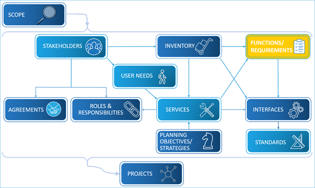
Figure 35. Regional ITS Architecture Components – Functions/Requirements
2.3.8.4 Approach
Whether this is an update to an existing architecture or the development of a completely new architecture the approach for the architecture's functionality involves organizing the data collected and decided so far and analyzing the requirements provided by ARC-IT as a starting point.
The next sections describe the different activities involved in each approach:
- Updating Functional Requirements
- Developing Functional Requirements
2.3.8.4.1 Updating Functional Requirements
Functional requirements in regional ITS architectures are defined for major elements in the ITS inventory. The requirements can be defined at two levels. The higher level is defined by the Functional Objects from ARC-IT that are mapped to each element through the mapping to physical objects of ARC-IT that is done in RADIT (see discussion below). For example, an element that is mapped to Traffic Management Center can select from 39 functional objects including functional objects such as TMC Traffic Information Dissemination, which is the functional object supporting the TMC functionality to operate dynamic message signs.
The lower level of functional requirements is when regional ITS architectures select a set of functional requirements for each of the selected functional objects. Again, this is done in RAD-IT (see discussion below). For example, there are 15 defined functional requirements for the functional object mentioned above, with the first requirement being "The center shall remotely control dynamic messages signs for dissemination of traffic and other information to drivers."
Updating Functions in the existing architecture involves reviewing the Functional Object selections for the key elements. Once the functional objects are updated, then the requirements themselves can be updated and the updated mappings outputted to the architecture website or document.
The update of the functional requirements in a regional ITS
architecture is best done once the ITS
inventory, the Service Packages, and User Needs have been revised. Then the update can be
accomplished on the Functions tab of RAD-IT using the Autoselect feature to
preselect the right functional objects and requirements.
There have been major
changes made to the functional objects in ARC-IT in the past few years, so it
is a good idea to review all the functional object mappings and revise as
necessary. It will be a good idea to spend some time reviewing the details
provided during the RAD-IT conversion process for the changes and use the
Autoselect feature to bring in the latest functional objects and requirements.
Functional requirements do not need to be generated for all the elements of an architecture, only for the ones that are being implemented by ITS stakeholders in ITS projects. In fact, for an element that is mapped only to terminators of ARC-IT, there is no functionality that will be available for mapping in RAD-IT. Therefore, if you want an element to have automatically-defined functionality, then the element must be mapped to at least one subsystem of ARC-IT. User defined functional objects and requirements will have to be defined for elements that are mapped only to terminators; this should be done only if the elements will be implemented by ITS stakeholders as part of ITS projects.
2.3.8.4.2 Developing Functional Requirements
Functional Requirements are defined for elements in a regional ITS architecture. See the discussion in Updating Functional Requirements above for a further description of how these functional requirements can be defined for a regional ITS architecture.
Functional requirements should be developed for elements in the regional ITS architecture. As discussed in the Inventory component, an inventory will normally include elements on the boundary of ITS that don't directly provide transportation services, but do exchange information with ITS elements. The classic example of an inventory element that is on the boundary is a financial institution that interfaces with ITS elements to support financial transactions. In general, a regional ITS architecture should include functions for ITS elements and should not include functions for ITS elements on the boundary.
An architectural boundary should be established to determine where functional requirements are needed. There are several ways to establish this boundary.
1. Perhaps the best approach is to consider whether each ITS element in the inventory will be implemented or enhanced with ITS projects implemented by the region's stakeholders. ITS elements that are implemented or enhanced with ITS projects are inside the ITS boundary and should include functional requirements. This may be the most definitive criteria for a regional ITS architecture boundary since this reflects one of the best uses for functional requirements. . .they are a starting point for ITS project specification.
2. Is the ITS element in this region, or in another region that is subject to the requirements of another regional ITS architecture? ITS elements in other regions probably should not be functionally specified.
3. Consider the services that are provided by the ITS element. If the ITS element provides surface transportation-related services, then it is probably inside the architecture boundary and should be supported by functional requirements.
4. Review how the ITS element was mapped to the ARC-IT. ITS elements that map only to ARC-IT terminators may be on the boundary; ITS elements that map to ARC-IT subsystems may be inside the boundary and include functional requirements. If you have an element that is only mapped to terminators, but is one that is being implemented or enhanced through an ITS project, consider reviewing the mapping to ARC-IT to include a mapping to the subsystem that most closely matches the functionality of the element.
Once your boundary has been established of what's inside and outside your functional boundary it's time to build on the services, needs, and operational concept to define functional requirements, focusing on those with regional implications.
Using the information gathered previously, document the functions required to support the services the stakeholders decided to provide for the region. Draft the starting set of functional requirements and refine them as you get closer to deployment.
Once the inventory of elements have been defined in RAD-IT then
functional requirements can be defined (See the RAD-IT
tab discussion for this component). This can start with a selection of
Functional Objects for the element. This selection will build on the ITS
service package choices and user needs defined for the stakeholder and element.
When selecting and customizing requirements a suggestion is to focus on those elements with regional implications. The functional requirements can be documented best on an architecture website, which can list both functional objects and functional requirements assigned to elements.
2.3.8.5 RAD-IT
The key information about system functional requirements is found on the Functions tab of RAD-IT. The updates to Functional Objects mentioned above is performed on this tab. As shown below, for each element there is a list of functional objects. This list is based on the physical objects mapped to the element. The Autoselect button will allow selection of a set of Functional Objects based upon which service packages in which the element participates.

Figure 36. Functions Tab in RAD-IT
Selecting the Requirements button will open a new window that shows all the requirements defined for the selected Functional Objects. The figure below shows a subset of the Requirements for the element selected above. Note that some requirements are included and some are not, indicating that these requirements have been customized. Additional customization is allowed by tailoring requirements or creating new requirements.

Figure 37. Functional Requirements Form in RAD-IT
In regional ITS architectures, many elements, particularly center
elements are mapped to multiple physical objects. If for example, you had
mapped a center element to Maintenance and Construction Management Center
(MCMC), but after completing customization on the Function tab find that no
MCMC Functional Objects are selected, then it is likely you did not need that
element mapping to the MCMC and should delete it on the Elements tab.
Opinions vary on how much effort to spend customizing functional requirements as part of a regional architecture effort. Requirements analysis is a key activity once a project begins its systems engineering effort. Using RAD-IT to automatically select a set of requirements based on the Inventory, Service Packages, and Needs for the regional architecture and then letting the requirements that come from ARC-IT be the starting point for customization once the project starts maybe a good middle-ground approach. If you know of projects that will be defined from this regional architecture then it may be worthwhile to the stakeholders to go ahead and start customizing the functional requirements. These customized functional requirements in the project architectures will then be available for additional systems engineering effort when using the SET-IT tool to create more detailed project architectures based on the project architecture in RAD-IT.
2.3.8.6 Examples
Examples of System Functional Requirements can be found in most regional ITS architectures if the region created an architecture website. For those architectures that create a website based on the RAD-IT tool, the following requirements information is provided for each element by selecting the Functionality link(s) on the Element detail page. The example below is from the Denver Council of Governments (DRCOG) Regional ITS Architecture.

Figure 38. Functional Objects Output Example
This web page provides the Functional Object level definition of the requirements. Access to the actual functional requirements is through the Functions tab on the home page which provides a list of the Functional Objects selected for the architecture (organized by Physical Object). An example of that page from a web site created for the Nashville Region is shown below. Selecting any of the Functional Area links provides a list of all the functional requirements from ARC-IT associated with the Functional Object.

Figure 39. Functions Web Page Example
Clicking on one of the Functional Areas (another name for Functional Objects from ARC-IT) will then show the functional requirements for those areas and the elements from the inventory that are assigned to those functions. See the page below for the Emergency Data Collection functional area from the Nashville Architecture.

Figure 40. Functional Requirements Web Page
2.3.9 Interfaces
This part of the architecture identifies the information to be exchanged between systems.
2.3.9.1 Definition
Interfaces include the electronic exchange of information between ITS elements. Interfaces can be defined by at two levels:
- Interconnects: Communications paths that carry information between elements. The majority of the interconnects are various types of communications links. Some of the key types of communications links relevant to regional ITS architectures are Center to Center (C2C), Center to Field (C2F), Field to Field (F2F), Wide Area Wireless (WAW), and Short Range Wireless, including Dedicated Short Range Communications (DSRC).
- Information Flows: Information that is exchanged between elements, including a high-level description of the information transmitted from one element to another.
2.3.9.2 Summary
|
POLICY
|
Interface requirements and information exchanges with planned and existing elements are a required component of the regional ITS architecture as identified in 23CFR940.9(d)6 and FTA National ITS Architecture Policy Section 5.d.6.
|
|
APPROACH Key Activities
|
If updating an existing regional ITS architecture: - Update Information Flows based on updates made to inventory, services, etc. Use RAD-IT to select and customize interface changes. - Regenerate outputs - Review with stakeholders, ensure they agree with the identified changes
If defining a new regional ITS architecture: - Identify Connections o Use the inventory, services, etc., to identify potential interconnections - Define Information Flows o Use ARC-IT to identify potential information to be exchanged o Use the interconnect-level decisions by the stakeholders and define the information flows exchanged on each interface o Document the high-level status for each information flow - Build Consensus o Review connections and information flows to ensure stakeholders agree with the identified interfaces for their ITS elements.
|
|
INPUT Source of Information |
- Stakeholders - Regional communications strategies/plans, other ITS Plans, TIP, STIP, etc. - Inventory of existing and planned ITS elements in the region - Regional needs and services, and operational concept
|
|
OUTPUT Results of Process |
- Definition of information to be exchanged between ITS systems in the region in diagram and table form
|
2.3.9.3 Relationship to Other Components
As shown in the figure below, each interface is connected to the ITS elements, and services, and standards. Inventory elements are needed to create an interface and are fundamental to providing Services. In addition, standards are defined for each interface and the requirements associated with inventory imply interfaces to the inventory elements. Any updates to these components will affect the connections between elements and the information exchanges between them. The relationship between interfaces and requirements is that some of the requirements assigned to inventory elements relate to the interfaces that exist for the element.

Figure 41. Regional ITS Architecture Components – Interfaces
2.3.9.4 Approach
Whether you are updating an existing architecture or starting a new architecture the definition of interfaces is an important and detailed part of the process. Stakeholder input is key to ensure agreement especially when interfaces extend across agency boundaries.
The next sections describe the different activities involved in each approach:
2.3.9.4.1 Updating Interfaces
The ITS inventory, services (and needs), and operational concept, lay the groundwork for evaluation of which ITS elements should connect to each other to exchange information. In case of a regional ITS architecture that is being updated, after the region's elements has been reviewed and updated, the current regional needs and services are understood, and an operational concept has been updated to reflect the current integration opportunities in the region in a broad sense, the interfaces will be reviewed and updated.
Developing interfaces can be done effectively with a two-step process of determining interconnects and then defining interfaces for the selected interconnects (which is described below in the Developing Interfaces section). In the case of updating an architecture, defining interconnects can be effective for new stakeholders with new elements, but in most cases the update can focus on updates to information flows in the architecture.
2.3.9.4.1.1 Update Information Flows
There are many ways to approach updating flows, but an effective approach is to start with evaluating the selected service packages to decide which stakeholders and ITS elements make up the revised or new service packages and then review the actual information that flows between the ITS elements in order to support the region's desired services. The approach continues with small revisions to the regional ITS architecture information flows based on corrections, revised stakeholder needs or updated status of information flows (e.g. from planned to existing). Other approaches to updating the information flows might focus on interfaces to a specific element (replicated over the key elements), or reviewing project interfaces to define a set of updates.
No matter what approach is used, the updated interfaces should include all connected source and destination ITS elements, a descriptive name for the information flowing between them, and a high-level status of that information flow (existing, planned, future, etc.). Adding a brief description or assumptions will be a good reference for future updates. All of these updates should be entered into RAD-IT.
2.3.9.4.1.2 Review Updates with Stakeholders
The next step is to gather stakeholder input on the updated information flows. This can be done by reviewing service package interfaces, element interfaces, or project interfaces, depending on the approach used to create the updates. This review can be facilitated by service package diagrams or other diagrammatic information. Web based information on the interfaces is another way to get stakeholder input.
When most of the stakeholders are present, concentrate primarily on
evaluating the information flows between centers, as those are most likely to
cross agency or public/private boundaries. Since an agency typically owns its
own center and respective roadside or vehicle assets, the information flows on
those internal agency interfaces really require only the evaluation of the
affected stakeholder, and not the stakeholder group at large. Consider handling
these non center-to-center information flows outside the general meeting.
2.3.9.4.2 Developing Interfaces
When developing interfaces for the first time, the approach also relies on initial definition of the inventory, needs and services, and operational concept, which lay the groundwork for evaluation of which ITS elements should connect to each other. Based on this information and any documentation that may describe existing communications in the region, a preliminary set of connections can be identified. A common approach to creating the set of interfaces is to first identify the interconnects between ITS elements and once those have been identified to look at the full set of information flows needed for the interconnects.
While this two-step "interconnects and then information flows" process for defining interfaces is not the only approach, experience shows that it is usually faster and easier to define interconnects first before specifying information exchanges. One reason to start with interconnects is that there are many more potential information exchanges than there are interconnects. The difference may be an order of magnitude – for example, 2000 potential interconnects vs. 20,000 potential information flows in a regional ITS architecture. Typically, only 20-30% (or approximately 400 to 600) of the valid interconnects will actually be selected for the region, effectively reducing the number of information flows that must be considered by 70-80%. Clearly, it is an iterative process, but use this Interconnect step to filter out all of the unwanted connections as early in the process as possible.
2.3.9.4.2.1 Identify Connections
Beginning with a preliminary set of interconnects, the stakeholders involved assess whether the interconnects would help support the needs and services of the region. Consider whether the connection exists today, or whether it is planned for the future. Often, a communications or network architecture is already in place between major "centers" in the region. Make sure the network can accommodate the connections identified in this step.
When most of the major stakeholders are present, concentrate primarily on evaluating the potential connections between centers, as those are most likely to cross agency or public/private boundaries. Since an agency typically owns its own center and respective roadside or vehicle assets, the connections to those items really require only the evaluation of the affected stakeholder, and not the stakeholder group at large. Consider handling these interconnections outside of general region-wide meetings.
Consider the existing connections between various stakeholder agencies, companies, or groups as the regional ITS architecture interconnects are defined. Many of these existing connections will be voice communications between people, either by telephone or face-to-face due to co-location of agencies such as public safety and traffic management agencies. The usual approach to architecture development is to focus on technical integration of elements, so they do not include voice interfaces that have no potential for conversion to, or augmentation with, data communications between two elements. In this case, only voice connections between people that may someday be supplanted or supported by data connections between elements are shown in the architecture as planned interconnects.
2.3.9.4.2.2 Define Information Flows
Now that the stakeholders have reached consensus on the interconnectivity of the ITS elements in the inventory, they must define the information that must be exchanged, given the services to be supported.
Each information flow is fully described by a source element (where the information originates), a destination element (where the information is sent) and a descriptive name for the information itself. The high-level status of the information flow (e.g., existing or planned) should also be documented.
Although each region can define their own criteria for flow status assignments, a reasonable approach is to consider whether the regional ITS architecture will have any impact on the information flows that are somewhere between "existing" and "planned" because implementation has started. For example, if the interface design is complete and ITS standards decisions have already been made, then the information flow may be considered to be "existing" with respect to the regional ITS architecture, even if the interface may not yet be operational. Following this criteria, information flows that can be influenced by the regional ITS architecture are designated as planned. Flows for interfaces that have already been designed are identified as existing. This approach has the added benefit of extending the "grace period" after the architecture is completed when the flow status will still be accurate when compared to criteria that only consider whether the interface is operational.
For flows that do not exist, RAD-IT provides the ability to define more
than one "planned" status. For example, some regions have used "planned" for
those flows expected to be implemented in the next 5 years and "future" for
those flows planned for implementation later than that. The majority of regions
do not go to this level of detail because it does it does increase the
complexity of the update process as you have to make decisions about thousands
of flows each update.
It is often helpful to review the operational concept and services established earlier, and envision the possible scenarios in which information is exchanged. This exercise often brings to light any gaps in understanding the operational concept since it reconciles the information sent by the source ITS element with the information expected by the destination ITS element.
When most of the stakeholders are present, concentrate primarily on evaluating the information flows between centers, as those are most likely to cross agency or public/private boundaries. Since an agency typically owns its own center and respective roadside or vehicle assets, the information flows on those internal agency interfaces really require only the evaluation of the affected stakeholder, and not the stakeholder group at large. Consider handling these non center-to-center information flows outside the general meeting.
Many regions use "hubs" to tie centers together that share information. For example, all public safety agencies in a region might be connected to an "incident information and mutual aid" network. All information exchanges between the public safety agency elements would go through this hub, facilitating region-wide sharing of information between agencies.
In some regions, the stakeholders think of the hub as a key component of the regional transportation system and feel it is important to include the hub in the regional ITS architecture. Explicitly including hubs in the regional ITS architecture has an ancillary benefit in that architectures that include hubs normally have fewer connections and information flows to define and maintain than equivalent architectures that depict point to point connections between all elements served by a hub. Other regions may decide that a "hub" is really a part of the communications infrastructure implementation and therefore should not be reflected in the interfaces defined in the architecture. Both views are valid. The region's stakeholders must decide which interpretation is best for their architecture.
There are a couple of factors to consider when deciding whether hubs should be included in the regional ITS architecture. One factor to consider is the functionality that the hub includes; a hub that implements ITS functions (e.g., data fusion) should probably be included in the regional ITS architecture while hubs that only implement communications functions (e.g., routing, protocol conversion, and data security) may be excluded at the stakeholders' discretion. This brings us to the most important factor in making this decision: Meeting stakeholders' expectations for the architecture by making sure that it reflects the stakeholder's "natural" view of the elements in the region. If the hub is largely transparent to the transportation professionals and other stakeholders, then it probably should be transparent in the architecture. If it is viewed as an integral part of the overall regional system, then it should be included as an important part of the architecture.
When hubs are included in a regional ITS architecture, a few key points should be documented. First, clearly define the element as a hub and include the functions that it performs in the definition. Second, document any specific interconnectivity constraints (e.g., a given public safety agency can NOT talk to another public safety agency using the hub in the above example) so that these selective connectivity requirements are not masked by the broad general connectivity that is suggested by a hub.
In some cases the information flows defined in ARC-IT don't cover the interfaces or information content that stakeholders view as important to their understanding of the architecture. In this case RAD-IT allows definition of user-defined information flows that can create interfaces or information not described in ARC-IT. One down side to creating user defined flows is that they will not have a set of standards associated with them like the ARC-IT information flows.
2.3.9.4.2.3 Build Consensus
Once the interfaces are defined in RAD-IT, they should be presented to the stakeholders for review and comment. Stakeholder reviews help build consensus around the interfaces that will be necessary for integration across the region. The information can be presented diagrammatically, in tables, or on a web version of the architecture.
When service package instances are used and ITS elements are associated
with the market package instances, RAD-IT can be used to show the interconnects
or information flows for one service package instance at a time, which greatly
facilitates the "customization" of these service package instances. Service
package instances can also be printed graphically one instance at a time,
facilitating use of service package instances in regional ITS architecture
development and maintenance.
2.3.9.5 RAD-IT
The key information about the interfaces can be found on the RAD-IT Interfaces tab, where the tool allows the user to define the interfaces between the transportation system elements in the region or project.
There are various views and customization options for this tab. The view below shows the information exchange tab, when the interfaces have been added for the region or project. For the information flows between elements, each information flow is described by a source element (where the information originates), a destination element (where the information is sent) and a descriptive name for the information itself. The high-level status of the information flow (e.g., existing, planned, future, etc.), and whether it is included in the architecture or not, are also shown in this view of the Interfaces tab.
RAD-IT also allows elements to be defined as communication elements (rather than transportation elements) and the communications used can be assigned to information flows as shown in the diagram below.
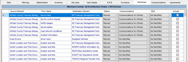
Figure 42. Interfaces Tab in RAD-IT
2.3.9.6 Examples
Interfaces are typically shown in several ways on architecture websites. The example below from the Ohio Kentucky Indiana (OKI) Regional ITS Architecture shows a typical Interfaces page which identifies for each element what other elements that it interfaces to. Each of these interfaces is an "Interconnect" in ARC-IT terminology.

Figure 43. Interfaces by Element Example
The websites also contain details about each interface, with an example shown below.
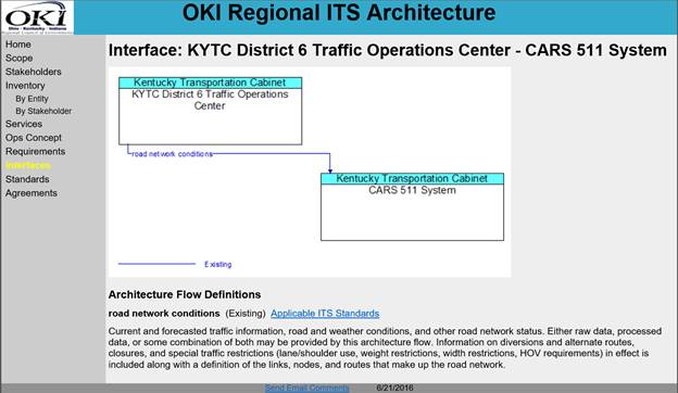
Figure 44. Interface Diagram Output Example
2.3.10 ITS Standards & Communications
Identifying which ITS standards to use in a region helps with the overall interoperability of the systems deployed among different agencies using different devices from various vendors.
2.3.10.1 Definition
ITS standards are documented technical specifications sponsored by a Standards Development Organization (SDO) to be used consistently as rules, guidelines, or definitions of characteristics. ITS Standards are primarily defined for interfaces between ITS elements, but they can also be defined for ITS elements as in the physical cabinet and traffic controller standards developed by the National Electrical Manufacturers Association (NEMA) and other organizations and Society of Automotive Engineers (SAE) standards developed for motor vehicles.
2.3.10.2 Summary
|
POLICY
|
Identification of ITS Standards supporting regional and national interoperability is a required component of the regional ITS architecture as identified in 23CFR940.9(d)7 and FTA National ITS Architecture Policy Section 5.d.7.
|
|
APPROACH Key Activities
|
If updating an existing regional ITS architecture: - Revise Standards List and Mapping o Update list based on updated interfaces o Review current standards usage with stakeholders
If defining a new regional ITS architecture: - Engage and Educate Stakeholders o Educate stakeholders on the importance of standards, especially with respect to cost, risk, and interoperability issues within the region and when connecting to neighboring regions - Identify standards for Region o Identify standards based on devices/interfaces selected o Identify other regional or statewide standards that might apply
|
|
INPUT Sources of Information |
- Regional Information Flows - USDOT web site (http://www.standards.its.dot.gov/) that provides status, deployment-based outreach, and lessons learned - Standards Development Organizations (SDO) websites, online technical discussions, and tutorials - Interface Control Documents (ICD) from all stakeholders' systems to identify standards currently in place.
|
|
OUTPUT Results of Process |
- Report containing a tailored list of physical and communications solutions and standards for the devices and interfaces in the architecture - Plan or Strategy for how ITS standards will be evaluated and implemented as ITS is deployed in the region
|
2.3.10.3 Relationship to Other Components
As shown in the figure below, ITS standards are mapped directly to interfaces. While not shown on the diagram standards have also been mapped when available to physical and functional objects so there could also be a line between the Inventory and Standards. Note that not all of the physical/functional objects or interfaces in the architecture have defined ITS standards but most do.

Figure 45. Regional ITS Architecture Components – Standards
2.3.10.4 Approach
Whether this is an update to an existing architecture or the development of a completely new architecture the approach for the architecture's standards involves making use of the latest information from ARC-IT to identify the appropriate and current standards and communications solutions for the selected inventory and interfaces. A discussion with the core stakeholders is also good to review the choices available and devise or update the strategy or plan for choosing, tailoring, and implementing standards-based solutions.
The next sections describe the different activities involved in each approach:
2.3.10.4.1 Updating ITS Standards
Updating the standards selections for an existing architecture are straight-forward once the inventory, services and interfaces are complete.
The new or modified interfaces represent potential new standardization opportunities. In addition, the standards identified with the other unchanged interfaces will likely have been updated since the previous version of the architecture. In addition, it is useful to gather information from regional stakeholders about their current use of standards.
ITS Standards primarily address interfaces between ITS elements, so updating the identification of ITS standards depends upon the update of the definition of the Interfaces. There are some basics to know prior to updating the list of communications solutions and ITS Standards. In general, each information flow has up to three types of standards that are relevant: a message set standard, a data element standard, and communications protocol standards. These are combined into a data profile and a communications profile which are then combined to make up a communications solution.
In the area of communications protocols, there are various technology choices that a region can make. Making the best choices depends on multiple factors, including throughput (how much data must be transmitted or received on the interface), maturity of the technology, network topology (how the ITS systems are connected together), infrastructure (fiber optic lines, leased land lines, etc.), and communications services (broadcast, publish/subscribe, etc.), among others.
In addition to communications standards to apply to interfaces a number of standards have been developed pertaining to the devices themselves. In ARC-IT these standards have been mapped as appropriate to the physical and functional objects. When RAD-IT is used and outputs are generated these standards will be shown alongside the Inventory pages.
The representation of standards in ARC-IT has been revised significantly from earlier versions of the National ITS Architecture and now provides more complete profiles of the set of standards applicable to different interfaces.
As described in the RAD-IT Tab for Standards below, there are two primary ways standards are represented in regional ITS architectures:
- Overall list of standards for the region
- Standards applicable to particular information flows between elements.
The overall list of standards is an output that can be created from RAD-IT and is commonly found in a section on standards in a document describing the architecture. The standards related to specific information flows cannot be edited in RAD-IT, but the information flow to standards mapping is available in tabular, document, and website outputs.
During the update process, consider creating a regional standards strategy or plan, if the original architecture does not include it (or updating any existing strategies or plans). This document shows how the region will migrate toward ITS standards. As part of that effort, stakeholders could reach consensus on an approach for ITS standards applicable to the region's interfaces. In addition, consider adding a discussion of the process for specifying standards for application in specific projects.
In determining when and how to incorporate ITS standards for a given
interface, it's critical to understand the relative maturity of the standards.
For each potential standard, consider asking:
- Has the ITS standard been approved or published by the Standards Development Organizations (SDOs)?
- Has the ITS standard been adopted by multiple vendors or system integrators?
- Has the ITS standard been tested, either informally by the vendor, or through the formal ITS Standards Testing Program funded by FHWA?
- Is there an amendment to the ITS standard or is a new version currently in the works, and if so, how much of the standard will change as a result?
2.3.10.4.2 Developing ITS Standards for the Architecture
For a new architecture there are some additional steps to consider when it comes time to identify the device and communications standards for the deployments of ITS in the region that are defined in the architecture. As with updating standards for an existing architecture this process comes after the inventory, services, and interfaces have been defined and agreed upon by the stakeholders.
2.3.10.4.2.1 Engage and Educate Stakeholders
The identification of ITS standards for a region occurs later in the development process, once inventory, services, and interfaces have been identified, but it can be helpful when developing an ITS architecture for the first time, to provide education to the stakeholders early on regarding ITS Standards. This can be done via a presentation on standards as part of engaging stakeholders in the architecture development process. The presentation can address the importance of standards, especially with respect to cost, risk, and interoperability issues both within a region and when connecting to neighboring regions.
 An extensive series of standards training modules is available from the
ITS Professional Capacity Building (PCB) Program (https://www.pcb.its.dot.gov/stds_training.aspx), which has developed a wide array of traffic and transit related
training modules covering most of the currently deployed ITS standards.
Information about these standards can be found at the USDOT ITS website at http://www.standards.its.dot.gov/. Also included on this website are contact numbers, standards
advisories, fact sheets, deployment lessons learned, peer-to-peer support, and
outreach material as well as links to websites maintained by the various
Standards Development Organizations (SDOs).
An extensive series of standards training modules is available from the
ITS Professional Capacity Building (PCB) Program (https://www.pcb.its.dot.gov/stds_training.aspx), which has developed a wide array of traffic and transit related
training modules covering most of the currently deployed ITS standards.
Information about these standards can be found at the USDOT ITS website at http://www.standards.its.dot.gov/. Also included on this website are contact numbers, standards
advisories, fact sheets, deployment lessons learned, peer-to-peer support, and
outreach material as well as links to websites maintained by the various
Standards Development Organizations (SDOs).
2.3.10.4.2.2 Identify standards for Region
The interfaces of the architecture provide a list of possible standards to consider. The details connecting interfaces to standards can be found on the ARC-IT website and in the RAD-IT database. In general, each information flow has up to three types of standards that are relevant: a message set standard, a data element standard, and communications protocol standards. These are combined into a data profile and a communications profile which are then combined to make up a communications solution.
In the area of communications protocols, there are various technology choices that a region can make. Making the best choices depends on multiple factors, including throughput (how much data must be transmitted or received on the interface), maturity of the technology, network topology (how the ITS systems are connected together), infrastructure (fiber optic lines, leased land lines, etc.), and communications services (broadcast, publish/subscribe, etc.), among others.
In addition to communications standards to apply to interfaces a number of standards have been developed pertaining to the devices themselves. In ARC-IT these standards have been mapped as appropriate to the physical and functional objects. When RAD-IT is used and outputs are generated these standards will be shown alongside the Inventory pages.
Decisions on technologies are generally not done while developing an architecture. They are usually done as part of ITS Strategic Plans, or when projects are deployed.
As part of this identification, review the
standards currently used by the stakeholders. It's possible that many industry
standards are already in use in the region. Encourage stakeholders to examine
their existing interfaces and determine whether this is indeed the case.
Discuss options for converting or translating these interfaces to make use of standards-based
solutions over time.
Along with understanding ITS Standards and how they might apply to the
region, consider also what others are doing. There may be decisions regarding
certain standards made by a DOT that are to be applied across the entire state.
Also, look at what neighboring jurisdictions and states may be doing. Working
together and sharing resources will reduce risk for everyone and increase the
integration between systems across the state and between states.
In addition to the interface standards that are being defined for ITS, a range of other regional standards may be considered that would facilitate interoperability and implementation of the regional ITS architecture. For example, standard base maps, naming conventions, measurement characteristics, georeferenced location standards, and organizational structure identifiers can all facilitate the meaningful exchange of information between systems in the region. These types of regional standards should also be considered and can be included in the standards documentation at the discretion of the region.
Regions may also want to consider creating a regional standards strategy or plan that shows how the region will migrate toward ITS standards. Documenting this strategy can help identify those standards currently deployed, those already planned for deployment, and identify issues that the region will need to address.
2.3.10.5 RAD-IT
ARC-IT maintains a mapping of information flows to ITS standards development activities. The Communications View pages of the ARC-IT website. Go to www.arc-it.net and select Architecture / Views / Communications. This includes the latest mapping between ARC-IT and the ITS communications standards. RAD-IT accesses this mapping information and makes it available for customization and tailored standards activity tables. The "Communications" tab in RAD-IT provides the opportunity to decide which of the communications solutions and ITS Standards activities best applies to the region. Use the Communications tab in RAD-IT to see the full list of standards are part of the architecture and use it when there are unique situations for your region, e.g. your state/region requires a certain standard interface for certain elements and you need to show that at the regional level.

Figure 46. Communications Tab in RAD-IT
RAD-IT provides an ITS Standards Report based on all of the information
flows selected in the region. The report lists all standards associated with
each architecture flow, either sorted by standard or by interface. Select the
specific ITS standards that reflect the regional standards strategy. When using
RAD-IT, try to minimize the number of user-defined information flows unique to
the region. Since ITS Standards are created using ARC-IT as a framework, any
user defined information flows in your architecture will not have these
industry consensus-based communications solutions and ITS Standards identified
for them.
 When you are developing a project, export the project architecture
information from RAD-IT into SET-IT and use SET-IT to build the physical view
(e.g. customized service package diagram with elements and flows) and then use
the Communications View to review the ARC-IT defined communications standards
for each layer of the relevant communications profile. By Using SET-IT you will
be able to see and customize the full interface protocols and standards
associated with each communications layer on an interface.
When you are developing a project, export the project architecture
information from RAD-IT into SET-IT and use SET-IT to build the physical view
(e.g. customized service package diagram with elements and flows) and then use
the Communications View to review the ARC-IT defined communications standards
for each layer of the relevant communications profile. By Using SET-IT you will
be able to see and customize the full interface protocols and standards
associated with each communications layer on an interface.
2.3.10.6 Examples
Examples of Standards can be found in every regional ITS architecture either in tables in an architecture document or on the architecture websites. For those architectures that create a website based on the RAD-IT tool, the following standards information is provided (the example is from the Central Ohio Regional ITS Architecture). The first example is the summary of standards applicable to the architecture.
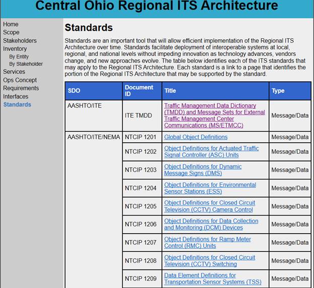
Figure 47. Standards Output Web Page Example
Selecting one of the standards identifies the flows to which this standard applies. The example below is a subset of the flows for the standard NTCIP 1203.
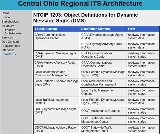
Figure 48. Interfaces per Standards Output Example
2.3.11 Agreements
Agreements between stakeholders define the integration planned between their systems, the plans for maintaining and operating the elements and each other's funding responsibilities.
2.3.11.1 Definition
To deploy the services and projects defined in the architecture, agreements between stakeholders may be required especially when inter-jurisdictional interfaces are involved. The architecture should list the agreements needed in order for cooperation and integration to be achieved, including how to deploy interfaces, who maintains and operates the elements, and how the operations will be funded.
2.3.11.2 Summary
|
POLICY
|
Any agreements (existing or new) required for operations, including at a minimum those affecting ITS project interoperability, utilization of ITS related standards, and the operation of the projects identified in the regional ITS architecture are required in 23CFR940.9(d)4 and FTA National ITS Architecture Policy Section 5.d.4.
|
|
APPROACH Key Activities
|
If updating an existing regional ITS architecture: - Revise existing list of agreements o Review new interfaces, services, or stakeholders o Add any new agreements or amend existing agreements to include new stakeholders, etc.
If defining a new regional ITS architecture: - Identify agency records/agreements that can be amended to include ITS - Utilize existing standard agreements for operations, integration, funding, etc. - Evaluate what kind of agreement is needed and build consensus with each of the stakeholders involved: o Memorandum of Understanding o Interagency Agreements o Intergovernmental Agreements o Operational Agreements o Funding Agreement w/ project scope and operations. - Agreements take a long time to execute. Build consensus early with simple agreements like MOUs while final agreements are being developed.
|
|
INPUT Sources of Information |
- Existing operational, intergovernmental, interagency and/or funding agreements between ITS element operating and user stakeholders. - Existing process and procedures for executing agreements between agencies. - Operational concept, interconnects, and project sequencing outputs from the regional ITS architecture.
|
|
OUTPUT Results of Process |
- List of inter-agency agreements required to deploy, operate, and maintain ITS in the region as defined in the regional ITS architecture
|
2.3.11.3 Relationship to Other Components
As shown in the figure below, agreements are mapped directly to stakeholders involved in the agreements. Although not shown in the diagram, some interfaces between elements owned by different stakeholders (but not all of such interfaces) in the regional ITS architecture might require data sharing agreements in order to be implemented.
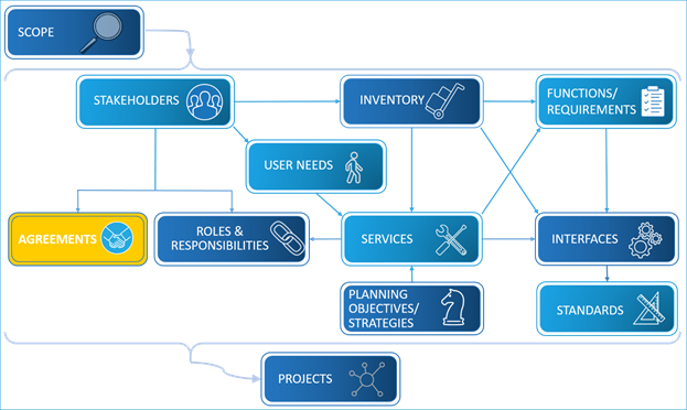
Figure 49. Regional ITS Architecture Components – Agreements
2.3.11.4 Approach
The "Update Existing" and "Develop from Scratch" approaches for drafting the list of agreements differ only in the starting point. Both require review and involvement by the stakeholders involved.
The next sections describe the different activities involved in each approach:
- Updating List of Stakeholders' Agreements
- Developing a New List of Agreements
2.3.11.4.1 Updating List of Agreements
Agreement are directly related to stakeholders. The architecture as previously defined will have a list of stakeholders that will serve as the starting point for the update. Start by reviewing the existing stakeholder agreements that support sharing of information, funding, or specific ITS projects. Review each agreement and determine whether the existing agreement needs be amended or modified to include additional new requirements for cooperation identified in the regional ITS Architecture. Decide if current agreements are sufficient until more specific operational agreements are identified in the future. If not, develop a list of required new agreements between agencies, perhaps a handshake agreement or a simple Memorandum of Understanding (MOU) will suffice in the interim. At any step of the work, ensure all stakeholders are aware of the required agreements and their status.
At this point, the list of required agreements is compiled and new agreements that must be created are identified. Note that all that is required is a list of the agreements, not the agreements themselves. The detailed work, including the preparation and execution of the identified agreements will be performed to support ITS project implementation later in the process. A fairly detailed understanding of the existing agreements in the region and the various options for structuring new agreements are critical to composing a realistic list of agreements.
In general, the process of building consensus for any agreements can build on the process of updating the regional ITS architecture: achieving regional consensus on needs, services, roles and responsibilities, and the architectural requirements on ITS elements, their functional requirements, information flows and standards for encoding the information flows. Once these institutional and technical issues have been agreed to, the foundation for the institutional agreements is in place.
There is considerable variation between regions and among stakeholders regarding the types of agreements that are created to support ITS integration. Some common types of agreements are shown in the table below.
Table 3. Types of Agreements
|
Type |
Description |
|
Handshake Agreement. |
- Early agreement between one or more partners - Not recommended for long term operations. |
|
Memorandum of Understanding. |
- Initial agreement used to provide minimal detail and usually demonstrating a general consensus. - Used to expand a more detailed agreement like an Interagency Agreement which may be broad in scope but contains all of the standard contract clauses required by a specific agency. - May serve as a means to modify a much broader Master Funding Agreement, allowing the master agreement to cover various ITS projects throughout the region and the MOUs to specify the scope and differences between the projects. |
|
Interagency Agreement |
- Between public agencies (e.g., transit authorities, cities, counties, etc.) for operations, services or funding - Documents responsibility, functions and liability, at a minimum. |
|
Intergovernmental Agreement. |
- Between governmental agencies (e.g., Agreements between universities and State DOT, MPOs and State DOT, etc.) |
|
Operational Agreement |
- Between any agency involved in funding, operating, maintaining or using the right-of-way of another public or private agency. - Identifies respective responsibilities for all activities associated with shared elements being operated and/or maintained. |
|
Funding Agreement |
- Documents the funding arrangements for ITS projects (and other projects) - Includes at a minimum standard funding clauses, detailed scope, services to be performed, detailed project budgets, etc. |
Consider the agreements needed for information sharing for integration,
which is one of the key reasons for developing the architecture. Also, avoid
being "technology prescriptive" in the initial agreements whenever possible
since technology changes rapidly. The technology selected during the planning
phase may well change as the project nears the final design phases. Of course,
there are times when technology is non-negotiable – the region may have an
agreement to use a specific standard or a legacy system must continue to be
supported or the region has already made significant investments in a
particular technology. In such cases, the agreements should reflect the
technology decisions that have been made by the stakeholders of the region.
2.3.11.4.2 Developing a New List of Agreements
The approach to developing a list of agreements mirrors that described above in the Updating Agreements section, just without the existing list to start from. As mentioned above, the architecture should contain a list of agreements and not the actual agreements. Through stakeholder interactions, identify existing agreements that are relevant to the regional ITS architecture. These would be agreements that address operations, maintenance, funding, etc. Next, consider any agreements needed to deploy ITS projects defined for the architecture. Agreements that support integration of systems in the region are especially important to consider and document, as these agreements are important to creating the system or data integration that is one of the key goals of deploying ITS in a region. Once agreements have been collected they can be entered into RAD-IT as described in the RAD-IT tab and reviewed by the stakeholders on the architecture website or in documentation.
2.3.11.5 RAD-IT Tab for Component
The Agreements Tab in RAD-IT is shown below and is the tab to use to enter and collect the list of existing agreements and the agreements potentially needed to deliver ITS services. Each list entry identifies the agreement title, the stakeholders involved, the type of agreement that is anticipated, high level status (existing or planned), and a concise statement of the purpose of the agreement.

Figure 50. Agreements Tab in RAD-IT
The RAD-IT Agreements tab has an Autoselect feature that is a good way to create your starting list. It can be used to analyze your architecture to come up with a proposed list of agreements. It will look at the interfaces tab and the inventory. For each interface where the source and destination elements are 'owned' by different stakeholders it will create a draft Information Exchange agreement.
2.3.11.6 Examples
The following example is a partial list of agreements taken from the Austin Texas Regional ITS Architecture. This regional ITS architecture identifies existing and planned agreements based on the projects developed for the region. This page is a part of the interactive architecture and for each of the agreements, the description and relevant stakeholders can be shown by selection the agreement title. An example of this, for the second agreement in the list is shown below.
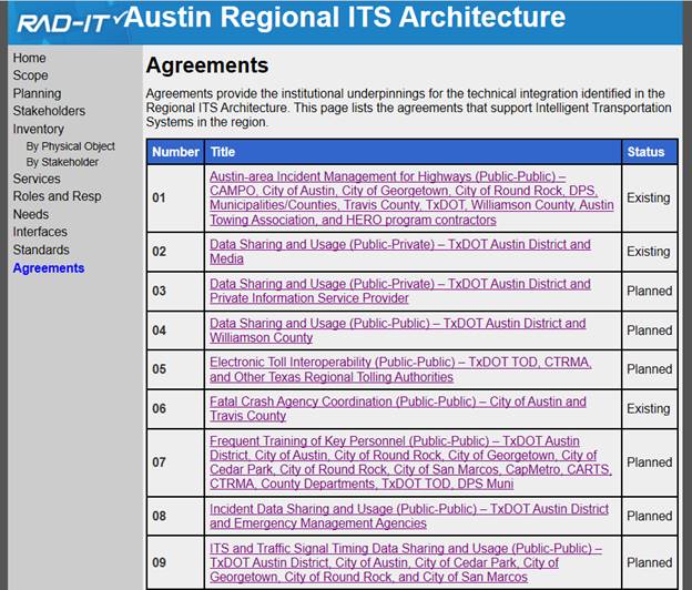
Figure 51. Portion of the Agreements for the Austin Regional ITS Architecture
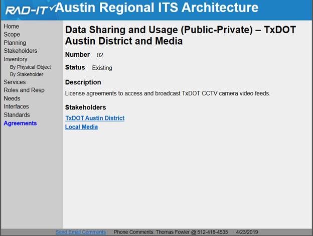
Figure 52. Specific Agreement from Austin Regional ITS Architecture
2.3.12 Project Sequencing
Defining a sequence of projects as part of the regional ITS architecture helps readers see just how things will be rolled out in their region.
2.3.12.1 Definition
According to CFR 940, Intelligent Transportation System (ITS) is defined as "electronics, communications, or information processing used singly or in combination to improve the efficiency or safety of a surface transportation system." An ITS project is any project that in whole or in part funds the acquisition of technologies or systems of technologies that provide an ITS service. Project sequencing is defined as any relevant ordering of the projects in order to contribute to the integrated regional transportation system depicted in the regional ITS architecture.
2.3.12.2 Summary
|
POLICY
|
The sequence of projects required for implementation as required in 23CFR940.9(d)8 and FTA National ITS Architecture Policy Section 5.d.8. |
|
APPROACH Key Activities
|
If updating an existing or defining a new regional ITS architecture: - Collect ITS Project Information o Gather initial project information from existing documents. o Gather project information from stakeholder via interviews, meetings, or surveys. - Define ITS Projects o Define ITS projects for the region in terms of the regional ITS architecture. o Define additional attributes of the projects such as Costs and Benefits o For each project define project ITS architectures within RAD-IT - Define Project Sequence o Identify the dependencies between ITS projects based on the inventory, functional requirements, and interfaces. Identify projects that must be implemented before other projects can begin. o Develop an efficient project sequence that takes the feasibility, benefits, and dependencies of each project into account. - Review Project Sequence with Stakeholders o Review details of project definition with stakeholders and revise as needed. o Create outputs summarizing project information on architecture website or in documents
|
|
INPUT Sources of Information
|
- Documents: TIP, STIP, the regional Long Range Plan, ITS Deployment (or Strategic) plans, Congestion Management Studies, and TSMO plans - ITS project dependency chart for the region or by agency if available. |
|
OUTPUT Results of Process |
- A documented sequence of projects, which can be used as input to the TIP, STIP, and other capital planning or operations planning activities
|
2.3.12.3 Relationship to other components
As shown in the figure below, each project in the project sequence can be defined as a subset of the components comprising the regional ITS architecture- components that address just the services, stakeholders, inventory, etc. associated with each project. The sequencing aspect of project is defined by the timeframe in which the project will be implemented.
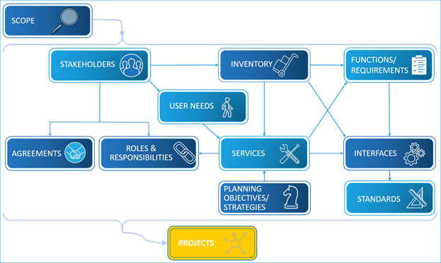
Figure 53. Regional ITS Architecture Components – Projects
2.3.12.4 Approach
The approach to project sequencing is the same whether you are updating and existing architecture or developing a new architecture.
2.3.12.4.1 Updating the Project Sequencing
The regional ITS architecture is "implemented" with many individual ITS projects that occur over the defined timeframe for the regional ITS architecture. A key aspect of an architecture update is to define a revised set of ITS projects that are planned for implementation in the region. A part of that definition will be the sequence, or ordering, of ITS projects that will contribute to the integrated regional transportation system depicted in the regional ITS architecture is defined.
One of the significant differences between ITS projects and conventional transportation projects is the degree to which information, facilities, and infrastructure might be shared between ITS projects. For example, a 511 Traveler Information System project may use information that is collected by previous instrumentation projects that collect traffic data and a CAD integration project that provides current traffic incident information. The regional ITS architecture allows the stakeholders to identify these ITS project relationships or "dependencies". Project dependencies can be used to identify project elements that must be implemented before other projects can begin. By taking these dependencies into account, an efficient sequence can be developed so that projects incrementally build on each other, saving money and time as the region invests in future ITS projects.
Both the traditional planning process and the approach to updating a regional ITS architecture have the same goal: to use a local knowledge, consensus process to determine the best sequence of projects to create a transportation network that best meets the needs of the people of the region.
The activities involved in updating a regional project sequence are virtually identical to those needed to create the project sequence initially, so for this component the discussion of the activities has been combined into a single thread.
2.3.12.4.1.1 Collect ITS Project Information
Projects are identified in planning documents like ITS deployment, strategic, or master plans that identify short, medium and long-term projects for a region. The TIP/STIP may include ITS related projects. At a higher level, long range plans may identify regional initiatives or priorities related to ITS. The first step in the update of ITS project sequencing process should usually be to review these plans, identify the ITS projects that are already prioritized as short, medium and long term, and then use this to begin to update the projects from the previous architecture development or update.
Beginning the ITS project update or development effort with any projecting sequence already included in applicable transportation plans is the best way to make sure that the completed project sequencing product will be relevant to planners and factored into future transportation plans. This two-way relationship between the regional ITS architecture products and the applicable regional planning documents is important to mainstreaming the regional ITS architecture into the transportation planning process. The relationship between the regional ITS architecture and the transportation planning process is described in more detail Architecture Use in Transportation Planning
.
The second input for project sequencing should be from key stakeholders in the region. As part of the interview step in the architecture update approach, review the existing set of projects from the architecture with the stakeholders and add, remove, or update projects as needed. One key to this discussion with the stakeholders is to consider projects with a longer timeframe, since many of the staff that are typically interviewed are more attuned to a short-term horizon.
In the case of developing a regional ITS architecture for the first time, data collection from the stakeholders (via interviews or meetings) should create a list of projects that are planned by the stakeholders. The same observation applies as in the previous paragraph- when discussing projects with stakeholders try to uncover some of their longer range plans that might be expressed as projects with longer timeframes.
2.3.12.4.1.2 Define ITS Projects
Each region (or potentially each stakeholder) should make a decision regarding the level of detail to be used for describing the projects. Many projects in regional architectures relate to deployment of field devices along specific roadways. Should the project name and description include details of the location (e.g. Third Ave) and number of devices (e.g. deploy 14 CCTV), or should it be defined as a more general "deploy new surveillance devices"? There is no "correct" answer to which level of detail is right for a particular region. In general, the level of detail contained in the TIP/STIP is likely the appropriate level to choose as it allows easy mapping of architecture projects to TIP/STIP projects.
For projects in the longer term, it may not be possible to identify specifics of the project but rather define the project in more general terms such as "ramp metering installations", "transit and traffic management information sharing", and "evacuation management system". These categories or even larger groups of projects can be defined as regional initiatives which can be included in long range plans as discussed in the section on Architecture Use in Transportation Planning.
In addition to defining projects at differing levels of detail, it is important to realize that it may take a series of projects to deploy a complex ITS system or initiative (e.g. Smart City Initiatives). As another example, ITS components such as surveillance cameras, message signs, signals, and ramp meters are not typically deployed across a region in a single project but in phases by roadway corridors. Since nearer term projects must feed into programming and budgeting processes, the phases of such projects could be identified in the project sequencing.
An architecture and the projects defined in it are not be fiscally constrained as in a TIP/STIP. An architecture is a plan for the future that would provide the ITS services desired for the region. The plan can be deployed as funding becomes available. It is important to consider projects beyond those currently funded as funding availability varies due to policy changes and other issues.
One of the key uses of a regional ITS architecture is to support ITS project development. This is described in the section Architecture Use for ITS Project Development. One of the first steps in using the architecture is to identify the portions of the regional ITS architecture that are implemented by the project. Because of this requirement, the regional ITS architecture needs to describe how the project maps to the architecture. One of the best ways to do this is to develop a project ITS architecture in RAD-IT for each project in a regional ITS architecture.
The project ITS architecture developed within the regional ITS architecture RAD-IT file should include key components of the regional ITS architecture including
1. Stakeholders
2. Inventory
3. Services
4. Information Flows
In addition, it is useful if the project ITS architecture also includes other components of the regional ITS architecture that are relevant to the project including:
1. Roles and Responsibilities
2. User Needs
3. Functional Requirements
4. ITS Standards
5. Agreements
Project information included in the architecture could include additional information that might make the regional ITS architecture more usable by the stakeholders. This information could include the following:
o Cost: Rough cost estimates for each planned project are an input to a realistic project sequence that takes financial constraints into account. Cost estimates should include both non-recurring (capital costs) and recurring (operations and maintenance) costs. Where possible, regions should use their own cost data as a basis. Cost basis information and assumptions should be documented to facilitate adjustment as additional data becomes available.
o Benefits: The anticipated benefits for the planned projects can also be used as an input to project sequencing. An estimate of benefits normalized by anticipated costs is a common figure of merit that can be used to identify ITS Projects that are the best candidates for early implementation. Both qualitative and quantitative safety and efficiency benefits may be estimated based on previous experience either within the region or in other regions that have implemented similar projects.
Documentation and tools are available to support analysis of benefits
and costs to support ITS project sequencing. The USDOT JPO has an ITS Benefits
Database and Unit Cost Database website that can be found at http://www.benefitcost.its.dot.gov/.
In addition to the databases, the website contains several documents
highlighting ITS benefits.
2.3.12.4.1.3 Define Project Sequence
In addition to defining the projects as described above, some effort should be undertaken to consider any sequencing or dependencies within the projects. The discussion below provides considerations relating to project dependencies and project sequencing.
With each ITS project defined in terms of the regional ITS architecture, the relationships between projects can be more easily identified:
- Where ITS projects share an information flow, there is an "information dependency" between the project that generates the information and the project that receives the information.
- Where ITS projects implement related functions on the same ITS element, there may be a "functional dependency" between the two projects. For example, certain core functions (e.g., surveillance) must be implemented before more advanced functions (e.g., incident verification).
In addition to the dependencies identified in the regional ITS architecture, ITS projects are also dependent on many other factors including the data or policy decisions that support the projects. For example, transit applications may be held up by the development of a bus stop inventory. A regional traveler information system may be held up by the lack of a regional base map. A regional fare system may be held up by a lack of consensus on regional fare policies. These types of dependencies should also be recognized and factored into the project sequence.
A project sequence defines the order in which ITS projects should be implemented. A good sequence is based on a combination of transportation planning factors that are used to prioritize projects and the project dependencies that show how successive ITS projects can build on one another. The most common "sequence" that regions use for their projects is a simple description of whether the projects are short term (often defined as "less than 5 years"), medium term ("5-10 years"), and long term ("greater than 10-years"). Any form of sequencing can be used by a region, this is just a commonly used format.
2.3.12.4.1.4 Review Project Sequence with Stakeholders
Once a project sequence has been defined or updated, it is important to review this with the stakeholders and gather comments on the detailed project information. Typically stakeholders provide a high level description of projects and it is left to the developers to define more precisely in terms of service packages, elements, and information flows how these projects are addressed by the architecture. Reviewing these details with the stakeholders will create a view of the project that matches their expectation and will often uncover additional project definition details that were lacking in the initial definition. Once the project sequencing is defined, outputs summarizing the project information can be put on architecture website or in documents.
As a sequence of projects is developed, also consider opportunities for
including ITS projects in traditional transportation construction and
maintenance projects that are planned for the region. Frequently, ITS elements
can be efficiently included in traditional transportation projects; these
potential efficiencies should be considered and reflected in the ITS project
sequencing. For example, dependencies between the traditional transportation
project and the ITS projects can be identified and the sequence can be aligned
so that the ITS project is deployed at the same time as the associated
construction and maintenance project. While efficiencies can be realized by
synchronizing ITS projects with traditional transportation projects, it may be
desirable to keep the capital improvements and ITS improvements contractually
distinct so that separate funding can be used and/or that the lower cost, but
possibly higher risk, ITS improvements can be more closely monitored and
managed.
 When project ITS
architectures are developed in RAD-IT, as described above, these can be
imported into the SET-IT tool in order to develop a more detailed project ITS
architecture and systems engineering documentation to support ITS project
development. See the SET-IT
tool page on the ARC-IT website for more information.
When project ITS
architectures are developed in RAD-IT, as described above, these can be
imported into the SET-IT tool in order to develop a more detailed project ITS
architecture and systems engineering documentation to support ITS project
development. See the SET-IT
tool page on the ARC-IT website for more information.
2.3.12.4.2 Developing a New Project Sequence
See "Updating the Project Sequencing". The process and approach is the same whether it is part of an architecture update or a new architecture development.
2.3.12.5 RAD-IT
In RAD-IT, ITS Projects are initially described on the Start Tab as shown below (which shows a set of projects for the sample database that is automatically downloaded when the tool is obtained). Note this sample database has 4 projects defined within this architecture and the first one is selected.

Figure 54. Start Tab from RAD-IT for Project Architectures
For a project architecture defined in RAD-IT, the same components can be defined as for the regional ITS architecture. In general, for each of the tabs in RAD-IT the starting set of information is that contained in the regional ITS architecture for that tab and the developer can select the subset of the information (from the regional ITS architecture) that is relevant to the project.
2.3.12.6 Examples
The following example of project sequencing come from the Chicago Metropolitan Agency for Planning (CMAP)'s Northeastern Illinois Regional ITS Architecture v.3.0 website. The first figure below show an excerpt from the Projects Tab of the website and the second figure shows a portion of the detail webpage for the first project in the list.
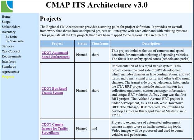
Figure 55. Example of Project Listing in a Regional Architecture
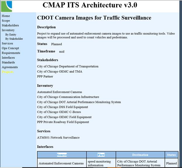
Figure 56. Project Information Detail from Regional Architecture Example
3 Regional Architecture Update/Development Approaches
Update (or development) of a Regional ITS Architecture occurs in the context of broader regional planning, programming, and project development processes. The relationship between the regional ITS architecture update approach is described below and the regional planning and programming processes is described in detail in Regional ITS Architecture Use in Planning/Programming. The relationship between the regional ITS architecture and the project implementation process is described in "Use in Project Development" (use section). Overtime, no matter how the architecture is used it will need to be maintained. See "Architecture Maintenance" for tips and steps on what to include in the maintenance of a regional ITS architecture.
3.1 Updating an Architecture
 Many different approaches can be used to update (or develop) a regional
ITS architecture. The approach described here is a suggested approach that has
been used by regions throughout the country, but it is NOT the only approach
that will result in an updated architecture that can be effectively used by the
region.
Many different approaches can be used to update (or develop) a regional
ITS architecture. The approach described here is a suggested approach that has
been used by regions throughout the country, but it is NOT the only approach
that will result in an updated architecture that can be effectively used by the
region.
Each region should employ an approach that works best for the unique set of institutional and technical conditions that define transportation planning and project deployment. Any approach that generates all the products that are required by the federal regulation can be followed to update an existing regional ITS architecture (or to develop an architecture if one does not currently exist). If your region doesn't have an existing approach, then the approach described in this section can be a good starting point for tailoring a regional ITS architecture update approach that best meets your needs.
The basic update approach can be described by the following general activities:
These steps represent general activities that will likely be iterated or performed in varying sequences depending on the stakeholder interaction during the update. Each step is described in more detail below. While these steps relate to the update of an architecture, with some slight variation they apply to developing an architecture for the first time (see the Developing a New Architecture discussion below).
3.1.1 Get Started
The regional ITS architecture effort begins with a focus on the institutions and people involved. Based on the scope of the region, the relevant stakeholders are identified, one or more champions are identified, the team that will be involved in architecture development is organized, and the overall development effort is planned.
Getting started with an update of the regional architecture – whether it's been 3 or 4 years or a decade or more – assumes that there's a good reason or need to update the architecture. The need to update an architecture is driven by change:
1. Changes in the elements and services that are in the architecture, maybe as simple as changing the things that were 'planned' a few years ago to 'existing'
2. Changes in the region itself – new stakeholders, new needs/services anticipated, growing populations centers, etc.
3. Changes in ITS as reflected in the national ITS reference architecture, www.arc-it.net.
Getting started also defines "who" will be involved with (and served by) the architecture and how the regional ITS architecture development will be structured.
Although a regional ITS architecture development effort is much smaller
than a major construction project in terms of financial expenditure, it is
institutionally complex because it is so inclusive. Architecture development
planning, particularly for outreach and consensus building, is an important
factor in a successful regional ITS architecture development. Allow sufficient
time for this outreach and consensus building when planning the overall effort.
As you get started with the update or development of a regional ITS architecture there are 4 activities to consider:
3.1.1.1 Identify the Need
After so many years of having intelligent transportations systems this may seem like a non-issue – Of course, we need an architecture! Or you may be saying, "We already have an architecture!" The decision to create and/or update an architecture may still be worth exploring to make sure the right stakeholders are involved in the decision and better prepared to take on the rest of the update.
Through this decision process, the development and maintenance of a regional ITS architecture is established as a shared objective by the transportation planning and operating agencies in the region.
 A regional ITS architecture is required by the FHWA Regulation (23CFR940) & FTA
Policy for regions that have deployed, or will be
deploying, ITS projects. An examination of the deployed ITS systems, the plans
for future ITS deployments, and system integration opportunities in the region
will establish if the regulation applies and a regional ITS architecture is
required. Every state and virtually every metropolitan region has some form of
ITS. While the regulation establishes a clear "requirement" for a regional ITS
architecture for many regions, the real "need" for a regional ITS architecture
is based more on its utility in ITS project planning and implementation.
A regional ITS architecture is required by the FHWA Regulation (23CFR940) & FTA
Policy for regions that have deployed, or will be
deploying, ITS projects. An examination of the deployed ITS systems, the plans
for future ITS deployments, and system integration opportunities in the region
will establish if the regulation applies and a regional ITS architecture is
required. Every state and virtually every metropolitan region has some form of
ITS. While the regulation establishes a clear "requirement" for a regional ITS
architecture for many regions, the real "need" for a regional ITS architecture
is based more on its utility in ITS project planning and implementation.
The most important reason to develop a regional ITS architecture is that it can help the region to efficiently plan for and implement more effective ITS systems. Thus, the ultimate objective is not to develop a regional ITS architecture that complies with a federal regulation, but to develop a regional ITS architecture that can really be used by the region to guide ITS implementation. A regional ITS architecture that includes all the products specified by the regulation but is never used by the region is not of real benefit to the region or US DOT. To meet the requirements of the regulation, the regional ITS architecture must be used to measure conformance of ITS projects on an on-going basis and be maintained as regional ITS requirements evolve.
The decision to proceed then should actually be based on a clear understanding and commitment by planning agencies, operating agencies, and key decision makers in the region that a regional ITS architecture is needed and will be put to good use. This implies that a decision to proceed should be accompanied by significant outreach and education on the benefits of ITS and system integration and the important role that a regional ITS architecture can play in developing these integrated systems.
There are many good resources available that can
support the outreach and education effort that may be required to realize the
benefits of a regional ITS architecture. USDOT has a website that lists
hundreds documents, web sites, training courses, software tools, and points of
contact covering all aspects of ITS, including ARC-IT and regional ITS
architectures. Check out the Resources page for the US DOT's ITS Joint
Program Office website.
3.1.1.2 Define the Region
The process of developing a regional ITS architecture begins with a definition of the region and captured as the 'scope' of the architecture.
The general scope of a regional ITS architecture can be defined in three ways:
1. Geographic Area: Define the geographic area covered by the architecture. What cities, counties, states, corridors, or other special areas does it include?
2. Timeframe: Define the planning timeframe that the regional ITS architecture will address. Should the architecture encompass systems and services that are implemented over the next five, ten, or twenty years?
3. Scope of Services: Specify the general categories of services that are included. For example, should the architecture cover commercial vehicle services?
See "Architecture Scope" in the Definition of a Regional Architecture for more information.
3.1.1.3 Identify Stakeholders to Participate in the Process
The success of the regional ITS architecture depends on participation by a diverse set of stakeholders. In the early stages of updating or creating a regional ITS architecture, the stakeholders in the regional surface transportation system are identified and the process of encouraging their participation in the regional ITS architecture development process is initiated.
Identification
of participating agencies and stakeholders is one of the required components of
a regional ITS architecture as identified in 23CFR 940.9(d)2 and FTA National
ITS Architecture Policy Section 5.d.2.
See "Updating Stakeholders" in the Definition of a Regional Architecture for more information on how this information is capture in the architecture.
Regions will vary dramatically in the degree to which the surface transportation system stakeholders are aware of ITS. In regions that have already implemented substantial ITS systems, the stakeholders have already been working together on many of the issues that will be addressed during regional ITS architecture development. As a result, these regions usually have existing ITS committees that will be a natural forum to kick-off the regional ITS architecture development.
Other regions will require more significant education and outreach efforts about ITS in general and the merits of a regional ITS architecture in particular to assemble and motivate enough stakeholders. When preparing education and outreach material to introduce stakeholders to the regional ITS architecture, it is a good idea to use local project examples that may already be familiar. If local examples are not available, a variety of excellent material is available from USDOT and other sources.
Educating the right people is important – frequently the education and outreach efforts will target the management levels in an organization where decisions can be made to commit valuable personnel resources to support the architecture development effort. Without management support, it will be difficult or impossible for those with a working knowledge of ITS in the region to participate effectively in the regional ITS architecture effort.
It is
often best to start with a core stakeholder group and then add participants to
the core group over time. The core stakeholders group would itself be a diverse
group with representation from each major agency and from both planners and
system operators. This core group provides continuity to the development effort
and an important set of contacts for the champion(s) and architecture
developer(s). Including too many stakeholders at the start can hinder regional
ITS architecture development progress and discourage people with limited vested
interest in the process. Although the architecture effort should be very
inclusive, a region may have better initial success if they are able to build
consensus among the stakeholders that plan/own/operate ITS systems first before
adding others into the decision making process.
The figure below shows a conceptual view of how stakeholders are added over time to the core stakeholder group. The core group is used to kick-off the effort. The number of active participating stakeholders increases as the architecture development effort begins to generate more detailed and varied products that require broad review and support. The number of active stakeholders may then begin to taper off as reviews are completed, comments are incorporated, and "completed" regional ITS architecture products are published. This same strategy of engagement can be used, but probably on a smaller scale, for periodic maintenance activities that follow.

Figure 57. Stakeholder Identification and Involvement over Time
While the number of active stakeholders begins to taper as the workload is reduced, the graph on the right shows that the total number of stakeholders will continue to increase over time, as different specialties and agencies participate in different parts of the architecture and different steps in the process. The perspective of the graph on the right is that once you are a stakeholder, you are always a stakeholder, although you may not actively participate beyond a specific milestone in the process. Over time, all relevant stakeholders in the region are engaged, just not all at once at the beginning of the architecture development effort.
If it is decided to initially limit the number of participants to a core group as depicted in Figure 57, set a timeframe to add others so that the architecture reflects the broader interests of the region. Table 4 in provides a list of potential stakeholders to consider.
Table 4. Candidate Stakeholders/Participants
|
Area |
Potential Stakeholders |
|
Transportation Agencies |
- State Departments of Transportation (DOT) - Local Agencies (City & County) o Department of Transportation o Department of Public Works - Federal Highway Administration (FHWA) - State Motor Carrier Agencies - Toll/Turnpike Authorities - Bridge/Tunnel Authorities - Port Authorities - Department of Airport or Airport Authority |
|
Transit Agencies/Other Transit Providers |
- Local Transit (City/County/Regional) - Federal Transit Administration - Paratransit Providers (e.g., Private Providers, Health/Human Services Agencies) - Rail Services (e.g., AMTRAK) - Intercity Transportation Services (e.g., Greyhound) |
|
Planning Organizations |
- Metropolitan Planning Organizations (MPOs) - Council of Governments (COGs) - Regional Transportation Planning Agency (RTPA) |
|
Public Safety Agencies |
- Law Enforcement o State Police and/or Highway Patrol o County Sheriff Department o City/Local Police Departments - Fire Departments o County/City/Local - Emergency Medical Services - Hazardous Materials (HazMat) Teams - 911 Services |
|
Other Agency Departments |
- Information Technology (IT) - Planning - Telecommunications - Legal/Contracts |
|
Activity Centers |
- Event Centers, e.g., stadiums, concert halls, convention centers, fairgrounds, ski resorts, casinos, etc.) - National Park & US Forest Services - Major Employers - Airport Operators |
|
Fleet Operators |
- Commercial Vehicle Operators (CVO o Long-Haul Trucking Firms o Local Delivery Services - Courier Fleets (e.g., US Postal Services, Parcel services, etc.) - Taxi Companies |
|
Travelers |
- Commuters, residents, bicyclists/pedestrians - Tourists/Visitors - Transit Riders, others |
|
Private Sector |
- Traffic Reporting Services - Local TV & Radio Stations - Travel Demand Management Industry - Telecommunications Industry - Automotive Industry - Private Towing/Recovery Business - Mining, Timber or Local Industry Interest |
|
Other Agencies |
- Tourism Boards/Visitors Associations - School Districts - Local Business Leagues/Associations - Local Chambers of Commerce - National Weather Services (NWS) - Air & Water Quality Coalitions - Bureau of Land Management (BLM) - Academia Interests, local Universities - National and Statewide ITS Associations (e.g. ITS America, AASHTO chapter members, etc.) - Military |
As additional stakeholders are added to the process, it may be a good idea to retain a core group that meets regularly and have a broader group that is included at selected milestones in the regional ITS architecture development. It is critical that all stakeholders participate enough in the process that they understand the architecture and feel some ownership of the process and the regional ITS architecture that is developed. It is important to continually encourage and validate participation of stakeholders in the development process.
It is
also important to focus stakeholder participation appropriately. For example,
both planners and system operators will participate in the process, but with
substantially different focus. System operators may be more interested in the
operational concepts, functional requirements, and interface definitions, while
the planners may have more substantial input while identifying transportation
needs and services and project sequencing. Other individuals with specialized
knowledge will be needed to assist in development of the list of agreements and
list of required ITS standards. As the "stakeholder roster" is developed,
consider the various areas of expertise that are required and use your stakeholder
resources selectively. Different stakeholders should be engaged in different
parts of the process, consistent with their expertise and interests.
Encouraging broad participation from many agencies, companies, and special interests in the region will occasionally bring people into the process who aren't really stakeholders in the regional transportation system. If the representative doesn't have, or plan to have, a system that should be integrated within the architecture timeframe or an interest in the surface transportation system as a whole (e.g., planners, the tourist industry, other special interests), then the representative is probably NOT really a stakeholder, will have little to contribute, and may ultimately grow frustrated with the process. It is best to understand the role of each potential new stakeholder in the surface transportation system at the outset and determine how they may contribute before significant time is invested. The objective is to be inclusive without wasting the time of those who do not have a vested interest.
Recognize
and respect that everyone's time is limited. Draw participants into the process
without bogging them down. Some useful techniques to encourage people with
demanding schedules to participate are to make sure everyone gets plenty of
time to review documents, and schedule short meetings with teleconferencing
options. This will help retain participants that may otherwise give up on the
architecture effort due to other commitments.
3.1.1.4 Identifying the Champion(s)
The champion(s) drive the process that must occur in order to develop a regional ITS architecture and build consensus at each step of the development. Without strong leadership, consistent meetings and a plan for completion of tasks, many of the participants will quickly become busy with other daily responsibilities. Regional ITS Architecture efforts that succeed all have a strong champion or champions to lead the effort and make it happen.
How do you identify champions? Many regions have already developed a team of ITS stakeholders that meet on a regular basis. Chances are that the champion(s) have already been identified by the fact that they are leading the regional efforts through an ITS Task Force, Technical Advisory Committee or the fact that they are already leading a major ITS project in the region. Adding regional ITS architecture consensus building to whatever "hat" these people are already wearing will be a natural transition. The process of identifying a champion or champion(s), and developing a task force to put the regional ITS architecture together should be woven into the existing regional planning process for ITS if one is already underway.
Champions are usually not voted-in; they are selected "on the job" in the course of working together. In many regions, a single champion will be identified. If there are several people who rise to the occasion, several champions can be identified that take turns leading the meetings or agree upon some shared responsibilities that will keep everyone engaged. A champion's skills include:
- Understanding of the subject (regional ITS architecture including familiarity with the National ITS Architecture)
- Knowledge of local ITS systems and projects
- Vision for interconnectivity, partnership, and regional integration
- Consensus builder (facilitator)
- Executive level access to resources to gain support for various regional efforts
The skill level that is needed in each area will vary depending on the technical and institutional maturity of the region. A more technically mature region may have many people with existing knowledge of the National ITS Architecture, but require increased skills in consensus building to pull various interests together. In institutionally mature areas that are growing in ITS technology, it may be a strong vision that guides the process. All of the identified skills are important for a strong successful champion along with the knowledge of when to use them.
No one individual is likely to possess all the knowledge and skills required to develop a regional ITS architecture. To be successful, the champion(s) must draw on the knowledge and skills of a diverse set of stakeholders. The champion is primarily a facilitator and manager and is not normally the one that actually defines the architecture – the stakeholders are.
A Champion must be a Stakeholder. It would be very difficult, if not impossible, for someone who did not have a vested interest in the outcome to be the champion for a regional ITS architecture development effort. A stakeholder who is already recognized in the region will best be able to take ownership and invest the time necessary to manage the regional ITS architecture development. FHWA, FTA, consultants, vendors and others are great participants, consultants may even do a lot of the detailed analysis and legwork in a regional ITS architecture effort, but for regional long-term benefit, they should not be champions.
Identifying
more than one Champion from varying backgrounds and disciplines (e.g., public
safety, transit, state DOT, city and/or county traffic engineering) can be a
benefit. A small group of people with diverse backgrounds and contacts can
strengthen the regional ITS architecture product by improving stakeholder
participation, encouraging agency buy-in, and facilitating access to the
information and resources necessary to support architecture development. Where
several champions are identified, they may form a steering committee (which
could also include representation from others such as FHWA/FTA) that manages by
consensus or advises and supports a leader who actually manages the development
and maintenance effort.
Identify Stakeholders introduced the idea of a core stakeholder group that would be involved throughout the architecture development effort. This group might be the small group of "champions" described in the previous paragraph, or it could be a larger group. No one model will encompass all regional ITS architecture development efforts. Each region must decide how they wish to organize their efforts. The key is that there is a group of stakeholders who plays a key role throughout the architecture development effort.
Champions will probably come and go over the evolution of developing
and maintaining the regional ITS architecture, and certainly will change over
the life of regional ITS system implementation and expansion. The task of the
Champion, like other leadership responsibilities, takes significant time.
Dividing the work among a few champions will limit the turnover and ease the
transition when one person leaves. It is important that good meeting minutes
and records of action items are kept so that new champions will have some
guidance regarding when, where, and why decisions were made.
3.1.2 Gather Data
Gathering data is a key activity that may occur several times during the update. The first period of data gathering, which will occur during every architecture update, occurs at the beginning of the update effort and will gather data regarding changes to the core components of the architecture. When the decision is taken to update an existing regional ITS architecture, it may be just a couple years since the last update or it may be a decade or more, so the scope of the changes will vary greatly depending on the timing of the update.
What data needs to be gathered during the initial phase of the update?
Updates to any of the following components described fully in Regional ITS Architecture Definition:
- Regional Goals, Objectives, and Strategies
- Stakeholders, including their Roles and Responsibilities
- Projects
The other components of a Regional ITS Architecture (e.g. functional requirements and standards) are details that are usually updated later in the process rather than at the time of this initial data collection. Many times changes to requirements, interfaces, standards, etc., will be derived from the changes made to the components listed above.
3.1.2.1 Approaches for Initial Data Gathering
When updating a regional ITS architecture, there are a variety of approaches for the initial gathering of the data listed above.
If the key stakeholders in the region are not familiar with the existing regional ITS architecture, which is often the case when the previous update occurred a number of years ago, then a good first step in the data gathering process is to have a kickoff meeting to bring the key stakeholders together and discuss the regional ITS architecture in general, the current architecture, and the steps that will be taken to update it. This type of meeting can get all the key stakeholders "on the same page" and motivate the work to come.
The data gathering can then commence using any of a variety of methods:
- Interviews (in person or by phone)
- Document reviews (including planning documents, e.g. metropolitan transportation plans, strategic plans, or TSMO plans)
- Stakeholder Surveys
3.1.2.2 Subsequent Data Gathering
Data gathering can occur at other times during an architecture update. Some of the times when this step may be repeated are:
- After initial architecture update
- After initial architecture review
The data gathered will likely be the same components described above. This data gathering may occur to close gaps in the initial data gathering effort, or to gather additional information from stakeholders after the initial architecture review.
3.1.2.3 Output of Gather Data Step
This step has two types of outputs
1. Summaries of data gathering inputs
2. List of architecture component changes to be used for the update.
The data collection summaries can be a complete set of all inputs obtained from stakeholders, or a summarization of key results. In the case of interviews or document reviews, a summary of results is the most likely outcome. In the case of stakeholder surveys, a complete set of the data collected is often the result. In some update efforts these summaries may be an actual deliverable, but equally often the data collected remains internal to the development process and serves as the input to the next step.
3.1.3 Update the Architecture
Once key regional data has been collected, the next key step is to create an update to the baseline of the architecture, specifically the RAD-IT file and any other files or documents developed previously.
3.1.3.1 Establishing the Architecture Baseline
A regional ITS architecture is defined by a baseline, which describes the documents, files, and website (if applicable) that make up the definition of the architecture. The most common parts of an architecture baseline are:
- A Regional Architecture Development for Intelligent Transportation (RAD-IT) file
- An architecture document that summarizes key components of the architecture and likely contains the maintenance plan for the architecture
- Website with a hyperlinked representation of the architecture
Additionally, the baseline could also contain:
- File of Service Package diagrams
- Change spreadsheet or database (to collect architecture changes requested since the previous update)
3.1.3.2 Updating the Baseline
The actual update of the baseline involves inputting the data collected into RAD-IT or the other baseline files. RAD-IT is organized around a set of Tabs that will need to be updated shown in the figure below:

Figure 58. RAD-IT Main Screen Showing Tabs for Input
The specific components of the regional ITS architecture that will need to be updated are shown below (along with the relevant Tab in RAD-IT if the Tab name differs from the component name). Each of these components is linked to a larger discussion that provides additional information on the component, how the component is represented in RAD-IT, update approaches, and examples of the component from other regional ITS architectures.
- Architecture Scope (on the Start Tab)
- Regional Goals, Objectives, and Strategies (on the Planning Tab)
- Elements (on the Inventory Tab)
- Services
- Stakeholder Roles and Responsibilities (on the R&R Tab)
- Requirements (on the Functions Tab)
- Communications and System Standards (on the Communications Tab)
- Projects (on the Start Tab)
The first step in the update of the RAD-IT (or Turbo Architecture) file
is to convert the starting file (from the last update of the
architecture) into the current version of RAD-IT. This conversion will be an
option the first time you open the starting file in the current version of
RAD-IT. Depending on how long it has been since the last update, the conversion
may cause a large number of possible changes to the architecture since the
underlying reference architecture (ARC-IT) has changed dramatically over the
years.
The changes impact all ARC-IT components and it is a very good idea to
review the Conversion table outputs to understand what has changed in the
architecture – both the regional architecture being converted and changes to
ARC-IT since your regional architecture was last updated.
The updates to RAD-IT can be entered into the file in whatever order the analyst decides, although it's often best to start with changes to stakeholders and elements as these are used in many parts of the update. The updates to RAD-IT and the other baseline files will likely occur several times during the overall architecture update. The goal of the initial set of updates, which usually are confined to the RAD-IT file and a file of Service Package diagrams, is to have a set of key updates that can be shared with stakeholders for review (see the Outputs step below).
An additional output that is usually created prior to stakeholder review is a web-based version of the architecture. RAD-IT has the capability of generating a simple hyperlinked website that represents all the components of the architecture that have been input to the RAD-IT file. In many cases this web-based representation of the architecture is used directly, or placed into an additional set of web pages that may expand upon the basic information generated by RAD-IT. While RAD-IT holds the details of a regional ITS architecture, it is not a particularly good tool for sharing information with stakeholders, with a website providing a more interactive and easily understood representation of the architecture.
Once an initial review of the architecture is held, the files will need to be updated again based on comments received, or additional data collected. The updates continue until the updating agency and the rest of the stakeholders reach consensus on the revised version of the architecture. At this point a final set of files is created and the project is completed.
3.1.3.3 Generating Outputs
Two key outputs from an architecture update are:
- Updated baseline files, e.g., RAD-IT, with the revisions based on data gathered or comments received from stakeholders.
- Material that can be used to provide stakeholder review. These could include some of the baseline files such as the architecture website and the updated service package diagrams. Additional outputs can be created out of RAD-IT to support stakeholder interaction such as tables to summarize stakeholders, elements, or other components.
You can use RAD-IT to regenerate a set of website files for a regional architecture. RAD-IT also has utilities to generate Word documents for a regional architecture that organize the contents of the architecture into a document format.
3.1.4 Reviewing the Architecture
In order to develop a consensus update to a regional ITS architecture, all of the updates made need to be reviewed with the relevant stakeholders. The inputs from the stakeholders will validate the changes to be made.
There are many ways that stakeholder review can be obtained including:
- Stakeholder meetings: Meeting with a variety of stakeholders is probably the best way to gather inputs. One of the key benefits of updating an architecture is the stakeholder interactions that occur in stakeholder meetings. It is rare in regional settings for operational stakeholders from a variety of disciplines to gather together to discuss their transportation plans. One of things that commonly happens at the meetings is that one agency will hear what capabilities another agency currently deploys, or what their plans for the future are and will say "I didn't realize you were doing that". While these meetings have traditionally been face-to-face, on-line meetings can be equally effective and may draw larger number of stakeholders.
- Website Review: As mentioned above, creating a website version of the architecture is an excellent way for stakeholders to review their part of the architecture. Whether as part of a meeting or off-line these reviews are essential to creating a useful architecture update.
- One-on-One Meetings: While stakeholder meetings are a good way to gather input, the likelihood is that the agency won't get all key stakeholders to a meeting(s), so one-on-one meetings with key stakeholders can help fill in the missing reviews.
In today's distracted world everyone has a lot of demands on their
time. If there is no way to gather people together for a large format meeting
or if a key stakeholder is not available then a webinar may help. A webinar
allows a presenter to control the flow and demonstrate key parts of the
architecture that need to be reviewed. Participants can ask questions and their
inputs can be recorded for review later.
Another key aspect of Stakeholder Review is a discussion of how the architecture will be used and maintained. Additional discussion of Architecture Use for Planning and Project Implementation is discussed on separate pages, as is a discussion of Architecture Maintenance.
An Architecture Review naturally happens once an initial Architecture Update has been performed, and differing aspects of Review will happen until the architecture update is finalized.
3.2 Approach for New Architecture Development Effort
The approach to be followed for a new architecture development effort or where the existing regional ITS architecture is more than a decade old is similar to that described above for an update. However, more time and effort may be spent on the tasks under Getting Started to set the stage for the development.
The high-level steps to create a regional ITS architecture are:
3.2.1.1 Get Started
If a region has never developed an architecture, or the original architecture is so out of date that it cannot really form the basis for an update, then the data gathering step will need to start with a couple of additional steps: Establish the need for the architecture, establish the scope, identify the stakeholders to include, and establish who will be the champion for the effort.
3.2.1.1.1 Identify Need
Before beginning development, a region should consider why they are developing the architecture. A regional ITS architecture is required by the federal regulation for regions that have deployed, or will be deploying, ITS projects. An examination of the deployed ITS systems, the plans for future ITS deployments, and system integration opportunities in the region will establish if the rule/policy applies and a regional ITS architecture is required. While the regulation establishes a clear "requirement" for a regional ITS architecture for many regions, the real "need" for a regional ITS architecture is based more on its utility in ITS project planning and implementation.
The most important reason to develop a regional ITS architecture is that it can help the region to efficiently plan for and implement more effective ITS systems. Thus, the ultimate objective is not to develop a regional ITS architecture that complies with a federal rule or policy, but to develop a regional ITS architecture that can really be used by the region to guide ITS implementation. A regional ITS architecture that includes all the products specified by the rule/policy but is never used by the region is not of real benefit to the region or US DOT. To meet the requirements of the rule/policy, the regional ITS architecture must be used to measure conformance of ITS projects on an on-going basis and be maintained as regional ITS requirements evolve. So, definition of a "concept of use" is important to a new development effort. This can be an actual document, or just the results of discussions among key stakeholders. The decision to proceed then should actually be based on a clear understanding and commitment by planning agencies, operating agencies, and key decision makers in the region that a regional ITS architecture is needed and will be put to good use.
3.2.1.1.2 Define the Region
The process of developing a regional ITS architecture begins with a definition of the region and captured as the 'scope' of the architecture.
The general scope of a regional ITS architecture can be defined in three ways:
1. Geographic Area: Define the geographic area covered by the architecture. What cities, counties, states, corridors, or other special areas does it include?
2. Timeframe: Define the planning timeframe that the regional ITS architecture will address. Should the architecture encompass systems and services that are implemented over the next five, ten, or twenty years?
3. Service Scope: Specify the general categories of services that are included. For example, should the architecture cover commercial vehicle services?
See "Architecture Scope" for more information.
3.2.1.1.3 Identify Stakeholders
The success of the regional ITS architecture depends on participation by a diverse set of stakeholders. In this step, the stakeholders in the regional surface transportation system are identified and the process of encouraging their participation in the regional ITS architecture development process is initiated.
Regions will vary dramatically in the degree to which the surface transportation system stakeholders are aware of ITS. In regions that have already implemented substantial ITS systems, the stakeholders have already been working together on many of the issues that will be addressed during regional ITS architecture development. As a result, these regions usually have existing ITS committees that will be a natural forum to kick-off the regional ITS architecture development.
Other regions will require more significant education and outreach efforts about ITS in general and the merits of a regional ITS architecture in particular to assemble and motivate enough stakeholders. When preparing education and outreach material to introduce stakeholders to the regional ITS architecture, it is a good idea to use local project examples that may already be familiar. Educating the right people is important – frequently the education and outreach efforts will target the management levels in an organization where decisions can be made to commit valuable personnel resources to support the architecture development effort. Without management support, it will be difficult or impossible for those with a working knowledge of ITS in the region to participate effectively in the regional ITS architecture effort.
See "Updating Stakeholders" for more information on how this information is captured in the architecture.
See "Identifying Stakeholders to Participate in the Process" for more about the way you include and educate stakeholders in the update or development of an architecture.
This is similar to the conversations and processes to involve the right operations stakeholders as part of FHWA's initiatives to advance Transportation System Management and Operations (TSMO). From FHWA's website here are some questions that start the conversation for TSMO and apply as well to regional ITS architectures:
- Who owns what routes in the transportation system? (Freeways, arterials, local roads)
- Are we coordinating with the right stakeholders? (State/Local DOT's, Cities, Counties, MPOs, Transit Authorities, First Responders, etc.)
- How are we tracking and monitoring the performance of our transportation system?
- How can we best utilize the data and metrics we have?
- What technology needs should we address to advance TSMO? Is our technology interoperable with other related systems and jurisdictions?
- Do senior leadership and other departments understand TSMO?
Find out more at https://ops.fhwa.dot.gov/tsmo/index.htm.
3.2.1.1.4 Identify the Champion(s)
See Identifying the Champion(s) in the section on Updating an Architecture. Whether this is a brand new architecture or an update to an existing architecture the process will need a champion to shepherd the stakeholders through the process. Having a good champion or two from the principle stakeholder agencies involved in the planning, deployment, operations, and maintenance of ITS is a key to the success of the development of an architecture.
3.2.1.2 Gather Data
Once the need for an architecture has been established, and the champion(s) identified, then the data collection will proceed in a similar fashion as for an update. See Gather Date in the section on Updating and Architecture.
3.2.1.3 Develop the Architecture
If a region has never developed an architecture, or the original architecture is so out of date that it cannot really form the basis for an update, then this step is about developing an architecture for the first time, rather than performing an update. Many of the steps mentioned in the "Update the Architecture" section still apply, but in the case of the RAD-IT file the region will have to start with a blank slate and develop the initial version of the components.
A recommendation is to start with the region's goals/objectives/strategies,
the lists of stakeholders, elements, services and projects to build an initial
version of the architecture. Convene reviews of the draft components of the
architecture as you go to help achieve early buy-in and continued motivation to
support the process. Once an initial version of the key components has been
developed then it can proceed much like the update steps listed above.
3.2.1.4 Review the Architecture
This step is essentially the same as described above. It is really important to engage stakeholders in meaningful ways to get them to provide their input. Using large format workshops, webinars, draft websites, and one-on-one interviews all play a part. See "Reviewing the Architecture" for more information.
4 Architecture Maintenance
Architecture maintenance is the set of procedures put in place by a region to describe the various options and considerations associated with on-going maintenance of the architecture products. This includes detailing the responsibilities for the maintenance as well as the procedures that need to be considered as an architecture is used and maintained over time. Much as ITS systems require planning for operations and maintenance, a plan should be put in place during the original development of the regional ITS architecture and updated as necessary each time the architecture itself is updated.
The development of an architecture maintenance plan and the implementation of a program to maintain the architecture is also a requirement of the ITS Architecture and Standards regulations as identified in 23CFR940.9(f) and FTA National ITS Architecture Policy Section 5.f, which say: "The agencies and other stakeholders participating in the development of the regional ITS architecture shall develop and implement procedures and responsibilities for maintaining it, as needs evolve within the region."
4.1 Overview
A regional ITS architecture is a plan for the deployment of ITS in a region. Once created, it needs to be updated via a maintenance process that can keep the plan current. The regional ITS architecture will need to be updated to reflect new ITS priorities, strategies and projects that emerge through the transportation planning process, to account for expansion in ITS scope, and to allow for the evolution and incorporation of new ideas. A maintenance process should be detailed for the region, and used to update the regional ITS architecture. This maintenance process should be documented as part of the initial development of the regional ITS architecture in a regional ITS architecture maintenance plan. The goal of the maintenance plan is to guide controlled updates to the regional ITS architecture baseline so that it continues to accurately reflect the region's existing ITS capabilities and future plans.
The purpose of maintaining a regional ITS architecture is to keep it current and relevant, so that stakeholders will use it as a technical and institutional reference when developing specific ITS project plans. A key characteristic of a successful regional ITS architecture is consensus; that is, the notion that each stakeholder has and continues to buy-in to the architecture as the model for how ITS elements have been deployed in a region, and more importantly how future ITS elements should be deployed in the region. A key consideration is Why a Regional ITS Architecture Needs to Be Maintained.
The maintenance of the architecture is driven by a set of maintenance decisions that define:
- Who: Roles and responsibilities for the maintenance effort
- When: Update timetable
- What: Architecture baseline
- How: the Approach to Architecture Maintenance, including the change management process and documented maintenance plan
The maintenance approach is meant to apply to a wide range of regional and statewide ITS architecture developments. Each architecture development effort will need to tailor the process to meet the needs and resources of their particular region.
4.2 Why Maintain a Regional ITS Architecture
The regional ITS architecture is not static. It must change as plans change, ITS projects are implemented, and the ITS needs and services evolve in the region. The regional ITS architecture must be maintained so that it continues to reflect the current and planned ITS systems, interconnections, services and other aspects of architecture. The following list includes many of the events that may cause change to a regional ITS architecture:
- Changes in regional needs. Regional ITS architectures are created to support transportation planning in addressing regional needs. Over time these needs can change and the corresponding aspects of the regional ITS architecture that address these needs may need to be updated. These changes in needs should be expressed in updates to planning documents such as the Regional Transportation Plan, the TIP, and the ITS Strategic Plan.
- New stakeholders. As new stakeholders become active in ITS the regional ITS architecture should be updated to reflect their place in the regional view of ITS services, elements, interfaces, and information flows. Why might new stakeholders emerge? The stakeholders might represent new organizations that were not in place during the original development of the regional ITS architecture. Or maybe the geographic scope of the architecture is being expanded, bringing in new stakeholders. Or maybe additional transportation modes or transportation services are being considered that interface with the systems of additional stakeholders.
- Changes in scope of services considered. The range of services considered by the regional ITS architecture expands. This might happen because ARC-IT has been expanded and updated to include new service packages or to better define how existing elements satisfy the user needs. A regional ITS architecture based on an earlier version of ARC-IT should take into consideration these changes as the regional ITS architecture is updated. ARC-IT may have expanded to include a service package that has been discussed in a region, but not included in the regional ITS architecture, or was included in only a very cursory manner. Changes in ARC-IT are not of themselves a reason to update a regional ITS architecture, but a region may want to consider any new services in the context of their regional needs.
 ARC-IT and its accompanying tool, RAD-IT are not updated on a set
schedule but on the basis of the program's configuration control process that
reviews and analyzes stakeholder inputs and works with US DOT to schedule when
the updates should be incorporated. Updates to ARC-IT and RAD-IT will be
publicized on the national ITS reference architecture web site: www.arc-it.net.
ARC-IT and its accompanying tool, RAD-IT are not updated on a set
schedule but on the basis of the program's configuration control process that
reviews and analyzes stakeholder inputs and works with US DOT to schedule when
the updates should be incorporated. Updates to ARC-IT and RAD-IT will be
publicized on the national ITS reference architecture web site: www.arc-it.net.
- Changes in stakeholder or element names. An agency's name or the name used to describe their element(s) undergoes change. Transportation agencies occasionally merge, split, or just rename themselves. In addition, element names may evolve as projects are defined. The regional ITS architecture should be updated to use the currently correct names for both stakeholders and elements.
- Changes in other architectures. A regional ITS architecture covers not only elements and interfaces within a region, but also interfaces to elements in adjoining regions. Changes in the regional ITS architecture in one region may necessitate changes in the architecture in an adjoining region to maintain consistency between the two. Architectures may also overlap (e.g. a statewide ITS architecture and a regional ITS architecture for a region within the state) and a change in one might necessitate a change in the other.
There are several changes relating to project definition that will cause the need for updates to the regional ITS architecture.
- Changes due to project definition or implementation. When actually defined or implemented, a project may add, subtract or modify services, elements, interfaces, or information flows from the regional ITS architecture. Because the regional ITS architecture is meant to describe the current (as well as future) regional implementation of ITS, it must be updated to correctly reflect how the developed projects integrate into the region.
- Changes due to project addition/deletion. Occasionally a project will be added or deleted through the planning process or through project delivery and some aspects of the regional ITS architecture that are associated with the project may be expanded, changed or removed.
- Changes in project priority. Due to funding constraints, or other considerations, the planned project sequencing may change. Delaying a project may have a ripple effect on other projects that depend on it. Raising the priority for a project's implementation may impact other projects that are related to it.
The above reasons for possible changes in the regional ITS architecture baseline may happen frequently or infrequently, depending upon the region and the specifics of the original regional ITS architecture development effort. This should be taken into account as one set of factors in determining how often to update the regional ITS architecture.
4.3 Who Is Involved in Architecture Maintenance Effort
Who will maintain the Regional ITS Architecture and what are their Roles and Responsibilities? Also, who will support the effort, and who will manage or have oversight for the maintenance effort? To maintain a consensus regional ITS architecture, to some extent all stakeholders will need to participate, but typically one or two agencies will take the lead responsibility to maintain the regional ITS architecture.
While responsibilities often reside with an individual within the primary organization, maintenance is a recurring activity and is necessarily a long-term effort. So, it is important that the agency responsible for architecture maintenance accepts that responsibility. The responsibility may be delegated to an individual at any given time, but the overall responsibility should be a stated role of an institution or agency in the region. In this way the responsibility transcends the variabilities that can impact an individual person's activities and career. Sometimes this responsibility will be shared by multiple agencies that are part of regional ITS coordinating councils or other groups.
If and when the individual
responsible for architecture maintenance leaves the organization make sure
maintaining the regional architecture is a part of the job description for
their replacement.
4.4 Maintenance Roles and Responsibilities
Two key considerations in defining roles and responsibilities for architecture maintenance are described below.
1. Does the agency responsible for architecture maintenance have the mission and authority to maintain the full stakeholder and functional scope of the regional ITS architecture?
The agency that maintains a regional ITS architecture ideally is one that has broad functional responsibilities across the full scope of the regional ITS architecture. In this case, "scope" represents the geographic area of the region, the transportation functions in the region, and the timeframe for deployment of new ITS elements and interfaces in the region.
A natural maintainer for many regions is the Metropolitan Planning Organization (MPO). Very often the scope of the MPO will match (or nearly match) the scope of the regional ITS architecture. In cases where the MPO does not possess the resources to manage the effort, or in cases where there is no MPO (e.g. if the "region" is a state) alternate maintainers might be identified. Some other possibilities for maintainer organizations are:
- State Department of Transportation (DOT). A State DOT might take responsibility for maintaining the regional ITS architecture. This particular approach makes the most sense for statewide architectures where the ITS functions are largely the responsibility of the state DOT. But it could also apply to regions that have limited resources available in the MPO.
- Transportation Authorities. These entities manage transportation infrastructure using a business model that may be relatively independent of those agencies more aligned with the MPO business model. If a Transportation Authority is a stakeholder in a regional ITS architecture, then an agreement between the Authority and the MPO may be necessary to carry on the appropriate maintenance of their common regional ITS architecture.
- Regional ITS Committees: Regions often have some institutional framework that make decisions about integration, ITS issues, operations, or procurement. Many areas in the United States address this issue by creating an ITS Committee, Working Group, ITS Program Committee, or Operations Task Force. This institutional group could be responsible for the architecture maintenance, but more likely will have responsibilities in supporting maintenance.
When one agency or institution takes responsibility for architecture maintenance, they may use agreements to create a management or oversight function (e.g. a "regional ITS architecture maintenance committee" or "regional ITS architecture maintenance board") to oversee regional ITS architecture maintenance work, which would have representation from the key stakeholders to the agreement. This group might be given management authority over the maintenance process. In this way, the stakeholders are investing in and controlling their own regional ITS architecture, and they will have direct responsibility for the quality of the product.
2. Does the maintainer have the necessary skills and resources to maintain the regional ITS architecture?
Depending on the approach used for architecture maintenance (see the Tab on Maintenance Approach) maintaining a regional ITS architecture can require a range of skills. In order to properly evaluate changes to the architecture the maintainer must have staff that is knowledgeable of the existing regional ITS architecture. This implies a detailed technical understanding of the various parts of the architecture and how changes would affect each part. Also required is an understanding of transportation systems in the region (although this understanding can reside jointly in the group of agencies/ stakeholders who participate in the maintenance process). Finally, the maintainer agency needs to have staff with an understanding of the tools used to create (and to update) the architecture. This might include for example, knowledge of the RAD-IT tool, if that is used to hold some of the architecture information. The agency responsible for maintaining the architecture needs to have the skills within its own organization or consider acquiring the skills. In either case, the agency needs the necessary funding to support the maintenance effort.
Having the resources to maintain a regional ITS architecture may mean that the stakeholders using the regional ITS architecture have to share in the costs to acquire these resources, even though one specific agency may commit to maintain staff or contract the skill set necessary.
3. What group will assist the maintainer in evaluating and approving changes?
Another decision that must be made is who will support the maintainer in evaluating and approving changes to the architecture. This should be a group of representatives of key stakeholders, ideally members from the areas of traffic, transit, public safety, and maintenance. This group might be a carryover from a committee or body that consisted of key stakeholders in the development of the architecture, or it could be a newly constituted group, or it might be a form of the Regional ITS Committee described above. These groups have many names, but one common trait – they often include both technical and managerial representatives of the key transportation agencies in the region.
The group responsible for evaluating and approving changes to the architecture may be a group that has some coordinating authority for integration of systems in the region. However there is no need for the group to have legal or contracting authority. They will be serving as a vehicle for consensus.
4.5 When – the Architecture Update Timetable
Another way to describe when the architecture will be updated is to consider what "timetable" will be used for making updates or changes to the architecture. There is no set timetable that will apply to every region. The timetable chosen will depend on several factors including how the regional ITS architecture is used and the funding/ staffing available for the task.
How often will the regional ITS architecture be modified or updated? There are two basic approaches to update interval: periodic maintenance and exception maintenance. Each has their advantages and disadvantages. They are not mutually exclusive, and an approach could be developed that is a combination of the two basic models.
- Periodic Maintenance. This approach ties the maintenance of the regional ITS architecture to one of the recurring activities of the transportation planning process. For example, if an MPO is the lead maintenance agency for a region, it's natural that the regional ITS architecture would be updated at the same frequency as the regional transportation plan is updated (every three to five years) or the Transportation Improvement Program is updated (at least every two years). The update of the architecture could occur prior to or following the transportation planning document update. If the architecture update precedes the update to the planning document the revised architecture could serve as an input to the planning update. The drawback to this approach is changes in support of ITS projects may not be updated into the regional ITS architecture on a timely basis. Publication and versioning costs are minimized for the periodic maintenance approach since there is a new version only once in the maintenance cycle.
- Exception Maintenance. This approach considers and makes changes to the regional ITS architecture in a process that is initiated as needed. This is very convenient for Federal Highway Administration (FHWA) Code of Federal Regulation (CFR) 940 consistency issues, but may be more costly than a periodic process (where requests for changes are queued until they are all addressed at once). Publication and versioning costs are dependent on the frequency of changes made to the regional ITS architecture.
- Combined Periodic and Exception Maintenance. This approach is the most responsive to stakeholder needs, and perhaps the most likely to succeed with regard to usage of the regional ITS architecture, however, it implies the greatest cost. Specific stakeholder requests are dispatched immediately, and a more thorough process of analysis is periodically applied to discover and incorporate new ITS requirements.
4.6 What – Defining the Architecture Baseline
What aspects of the regional ITS architecture will be maintained? Those constituent parts of a regional ITS architecture that will be maintained are referred to as the "baseline".
4.6.1 Architecture Components Baseline
All the components that have been developed for a regional ITS architecture should be maintained as part of the architecture baseline. These include:
Description of Region
This description includes the geographic scope, functional scope and architecture timeframe, and helps frame each of the following parts of a regional ITS architecture. Geographic scope defines the ITS elements that are "in" the region, although additional ITS elements outside the region may be necessary to describe if they communicate ITS information to elements inside the region. Functional scope defines which services are included in a regional ITS architecture. Architecture timeframe is the distance (in years) into the future that the regional ITS architecture will consider. The description of the region is usually contained in an architecture document, but should also reside in the RAD-IT file on the Start tab.
List of Stakeholders
Stakeholders are key to the definition of the architecture. Within a region they may consolidate or separate, and such changes should be reflected in the architecture. Furthermore, stakeholders that have not been engaged in the past might be approached through outreach to be sure that the regional ITS architecture represents their ITS requirements as well.
Connection of architecture to planning goals, strategies, and objectives
This component provides the connection between a regional ITS architecture and attributes used by regional planners for their transportation planning efforts. The connection between regional goals, strategies, or objectives and architecture service packages or projects provides the link between the needs of the community to the deployment of ITS.
Roles and Responsibilities
It is crucial that the roles and responsibilities in a regional ITS architecture accurately represent the consensus vision of how the stakeholders want their ITS to operate for the benefit of surface transportation users. These should be reviewed, and if necessary, changed to represent both what has been deployed (which may have been shown as "planned" in the earlier version of the regional ITS architecture) and so that they represent the current consensus view of the stakeholders.
List of ITS Elements
The inventory of ITS elements is a key aspect of the regional ITS architecture. Changes in stakeholders as well as Roles and Responsibilities may impact the inventory of ITS elements. Furthermore, recent implementation of ITS elements may change their individual status (e.g. from planned to existing).
ITS Services
ITS Services, defined in the architecture by a set of service packages and often a set of user needs, provide the key details on what ITS capabilities are currently deployed or planned for possible deployment in the region. The service packages define how the elements are connected to provide the ITS services.
List of Agreements
One of the greatest values of a regional ITS architecture is to identify where information will cross an agency boundary, which may indicate a need for an agency agreement. An update to the list of agreements can follow the update to the Roles and Responsibilities and/or interfaces between elements.
Interfaces between Elements (interconnects and information flows)
Interfaces between elements define the "details" of the architecture. They are the detailed description of how the various ITS systems are or will be integrated throughout the timeframe of the architecture. They are a key aspect of the architecture baseline, and one that will likely see the greatest amount of change during the maintenance process.
Functional Requirements
High-level functions are allocated to ITS elements as part of the regional ITS architecture. These can serve as a starting point for the functional definition of projects that map to portions of the regional ITS architecture.
Applicable ITS Standards
The selection of standards depends on the information exchange requirements. As projects are implemented and standards are chosen for a project they need to be reflected back in the regional ITS architecture so that other projects can benefit from the selections made. In addition, the maintenance process should consider how ITS standards may have evolved and matured since the last update, and consider how any change in the "standards environment" may impact previous regional standards choices (especially where competing standards exist).
Project Sequencing
While the definition of projects and project sequencing is partly determined by functional dependencies, e.g. "surveillance" must be a precursor to "traffic management"; the reality is that for the most part project definition and their sequences are local policy decisions. Project definition and their sequences should be reviewed to make sure that they are in line with current policy decisions. The update of projects and their sequences is a key aspect of any maintenance effort so that the architecture can continue to be used by project development activities.
4.6.2 Baseline Artifacts
While the components listed above constitute the architecture baseline, a key consideration is what documents, files or databases hold the information from these components. The most common artifacts are:
- RAD-IT file. This file contains the details of components described above
- Documentation. The most common documentation is an Architecture document that describes the different components and may contain the architecture maintenance plan. Some architectures put all the details of their architecture in a document (or documents), usually in lieu of having a web site. Sometime a maintenance or use plan are separate documents and sometimes chapters in a single architecture document. Documentation can also include spreadsheet information such as architecture changes planned for the next update.
- Diagram files. Some architectures create customized service package diagrams that are contained in separate applications such as Visio or PowerPoint
- Web files. Many architectures create a web-based version of the architecture. The set of files comprising the web site are another key artifact
In addition to the components of the architecture being maintained
above, it is also important to document the resources that were used along the
way to develop the architecture – the Region's Transportation Plan, TIP, ITS
Strategic Plans, TSMO plans, various studies, as well as other regional ITS
architecture. Document these other resources with their titles, dates or
versions, and where they can be found so that future maintainers can understand
some of the background that supported the development of this regional ITS
architecture and remember that changes to those documents may affect the architecture.
4.7 Maintenance Approach (How)
This section describes possible regional ITS architecture maintenance approaches, answering the question, "How is a regional ITS architecture maintained?" These approaches fall into roughly two options:
1. Architecture updates occur only at periodic intervals as specified in the maintenance plan. In general, little maintenance effort occurs between these periodic updates, although potential architecture changes may be collected by whatever agency or group is taking responsibility for the architecture. Some basic elements of configuration management are used to maintain the current version of the architecture. The vast majority of architectures developed fall into this category.
2. Architecture updates occur as needed to address new stakeholders, elements, services, or projects defined by the region. This approach is used by some regions to help address federal requirements for major projects that were not covered in the current architecture. This approach implies a somewhat more robust use of configuration management is needed to keep the architecture up to date and to make sure all the relevant stakeholders are informed of any changes made.
These two general approaches can apply to the maintenance of any regional ITS architecture, but should be tailored to fit the size and scope of each particular architecture. The approach should also be tailored so that it fits within the region's transportation planning processes, e.g., the Regional Transportation Plan update process.
4.7.1 Effort Required for Maintenance
How much effort must be expended to maintain a regional ITS architecture? That is dependent on several factors:
- How much activity is there that would involve use of the architecture? The more it is used to support planning and project development activities, the greater the level of changes it will probably see. Is the region going through a major update to their long-range plan? Is there a high-level of investment in technology in the region? Is the project activity concentrated in one department or agency or is it spread across several agencies in the region?
- What is the approach being used for architecture maintenance? Is it incremental changes or full baseline update?
- What is the maintenance update cycle? Are changes being incorporated on a regular basis or is revision of the architecture happening once every planning cycle?
- What is the size and complexity of the architecture? The larger the architecture the greater the effort in maintaining it.
To identify the effort required consider several maintenance scenarios:
1. The maintaining organization collects change requests and reviews them with the maintenance committee on a periodic (e.g. quarterly) basis.
How many changes are collected in each period is very dependent on use of the architecture (how much is it being looked at while stakeholders are using it) as well as the complexity of the architecture (how many elements or connections could be changed). Creating a change request should be a small-time investment for any submitter (e.g. under an hour of time). There is a small-time investment of the maintaining organization to log the changes. Periodically, changes would be evaluated and presented to the maintenance committee. Evaluating each change will take only a small-time investment. A maintenance committee meeting of a couple hours will dispose of the changes. The amount of effort required to update the baseline will be a function of the scope of the change (e.g. adding a new stakeholder, inventory items and connections will take longer than changing the status of a few information flows). Again, the amount of effort for the activities described above is dependent on the number of changes being considered.
2. The maintaining organization collects change requests and holds them until an update occurs X years after the initial architecture is completed.
This scenario is very similar to the previous one (in terms of time required for each change). The primary difference would be the number of changes to be incorporated. Again, the amount of effort will be highly dependent on such things as the level of ITS investment in the region. One way to limit the amount of effort required in the evaluation and approval part of the process is to have maintainer staff produce a summary of changes and recommended outcomes (approve, defer, or reject). This will allow the maintenance committee to focus on only those changes requiring significant stakeholder consensus when it meets.
3. At the update cycle stakeholders are brought back together for one or more workshops to review and update the architecture.
This is the full baseline update approach. In this approach, additional time will be spent getting some subset of the stakeholders together in one or more workshops to review the architecture. A series of changes will naturally flow from these meetings that can be incorporated en masse into the architecture. The level of effort required for these meetings will be dependent on how many meetings are planned and how much effort will be required to present the architecture to the stakeholders.
So how much will it cost? We all have to answer to the realities of budgeting and planning which forces us all to the bottom line. The cost of maintaining a regional ITS architecture depends on how you are going to use it. As you can see from the discussion above, the cost of paying someone to update the database, web site, and documents may be trivial compared to the cost of all of the stakeholders' time reviewing and approving changes. Think about the scenarios above and decide what maintenance approach your region will likely follow. Based on that decision you can then decide whether to allocate some financial resources to your future budgets to cover the cost of maintenance – personnel, equipment, contractors, etc. If the regional ITS architecture is going to be maintained by the MPO, then they should consider making architecture maintenance a work item in their Unified Planning Work Program (UPWP).
For more information consult FHWA's "Regional ITS Architecture Maintenance Resources: Technical Advisory" (available in HTML or PDF from https://ops.fhwa.dot.gov/its_arch_imp/resources.htm). It describes resources needed to effectively maintain a regional ITS architecture including; estimated resources needed (work-load and budget), variables that influence resource allocation, and situations where substantially more resources may be needed.
4.7.2 Configuration Management
Configuration Management (CM) is defined as: "A management process for establishing and maintaining consistency of a product's performance, functional, and physical attributes with its requirements, design and operational information throughout its life." CM can be applied to the development of any system. In the context of a regional ITS architecture it is a process for establishing and maintaining consistency of the architecture's information content throughout its life. In general, the configuration management process consists of five major activities:
- Configuration management planning – Before you start, there are some decisions that need to be made about what needs to be controlled within a product configuration, when you establish a controlled configuration, how you change a controlled configuration, and what amount of effort you're going to expend in managing configurations. In the context of maintaining a regional ITS architecture this corresponds to the architecture maintenance plan.
- Configuration identification – Identify what needs to be independently identified, stored, tested, reviewed, used, changed, delivered and/or maintained. Identifying the configuration items and what identifiers will be used is part of the architecture maintenance plan.
- Configuration control – Describe the process by which changes are made to the configuration baseline and when and how they are made.
- Configuration status accounting – Establish how you will keep track of the state of all configuration items, all pending proposed changes, and all approved changes to those configuration items.
- Configuration audits – Periodically verify the consistency of configuration documentation against the product. In the context of a regional ITS architecture this includes verifying that different representations of the architecture (e.g. document and database) match.
These activities are performed throughout the life of the development and operation of systems. Each of the activities described above can be described within the context of managing change as it relates to a regional ITS architecture.
4.7.3 Architecture Maintenance Process
This section takes the concepts of Configuration Management described previously (See CM section) and applies them to the approach needed to maintain a regional ITS architecture.
4.7.3.1 Planning
Before the maintenance activity begins the parameters of the activity must be identified and the details of the process must be determined. These parameters, defining who will maintain the architecture, when the architecture will be updated, and what will be the baseline maintained. These decisions and the maintenance process itself should be defined in an architecture maintenance plan, which is the primary output of the configuration management planning activity. The maintenance plan may be a separate document or part of the larger regional ITS architecture document. The plan should be created during the initial development of the regional ITS architecture. If it was not then the process should be defined and documented as soon as possible. The maintenance plan should also be a part of the architecture baseline described below.
Who
The maintenance plan should identify who will be responsible for the maintenance effort and what group of stakeholders will review and approve changes to the architecture baseline. In addition to defining who will be involved in maintenance a description of each agencies roles and responsibilities may be included.
What resources are needed to maintain an architecture?
In the context of maintenance of a regional ITS architecture, the same
personnel skills that are used to work with the RAD-IT tool and ARC-IT will be
used in managing the configuration items that are included in the configuration
management plan.
In addition to human resources, there will need to be file servers, web sites, or other central locations to store electronic copies of configuration items. These must be "read-only" and protected so that changes are not made to released versions of the databases and documents. Any required changes require a new version number/date and hence a new copy of the configuration item separate from the previous version.
When
The maintenance plan should also identify the timetable for regional ITS architecture updates. As discussed before, there are several options. The other timing decision that should be identified in the maintenance plan is when to set the baseline and begin the maintenance process. In the case of regional ITS architectures, the first release of the architecture after its initial development would normally constitute the initial baseline. This is the point at which the architecture is ready for distribution and use, and the point at which potential changes to the architecture may begin to develop.
What
The maintenance plan should clearly identify what will be maintained- i.e. the architecture baseline. In fact, these parts are contained in databases (e.g. a RAD-IT database), spreadsheets, drawing files (e.g. PowerPoint or Visio), Hypertext Markup Language (HTML) files for a web site, and documents. Defining the architecture baseline is defining exactly what documents, databases, etc. will be maintained.
In addition to these architecture outputs, source documents that were used to produce the regional ITS architecture outputs may also be important to identify. Some of these documents will be the subject of later revision and maintaining a consistency between the architecture and the other efforts is important. For example, if the regional ITS architecture inventory was derived from a number of individual stakeholder inventory documents, then the date and version numbers of those source documents should be considered for inclusion in your list of controlled items. Other examples of these source documents might include early deployment study reports, strategic deployment plans, and inventory tracking reports. It is important that the dates of reports and any version numbers associated with the reports are recorded as part of the configuration that is controlled. This way, subsequent releases of these documents would trigger an analysis to determine how the changes are best propagated through the rest of the controlled items in order to maintain a consistent configuration. It's also necessary to record where these are stored, e.g., at which agency, on which data server, web site or other storage location.
The versions of software tools that were used to produce the architecture might also be included in the set of configuration items. These might include the RAD-IT tool and the version of ARC-IT used. For these tools, the important thing to record as part of the configuration is the version number and date of release. Subsequent updates to the tools and databases would trigger a change analysis.
A final consideration that goes into the definition of the architecture baseline is how you plan to use the architecture. Will service package diagrams be an important source of interfaces for project definition? Or will interconnect diagrams be used? Or will project developers go directly to the database representation for their detailed definition? Considering some of these alternatives will help you decide which representations of the architecture are most important to your region.
The list below shows some examples of the items that might be selected for the architecture baseline.
- RAD-IT Databases
- Regional ITS Architecture Documentation
- Maintenance Plan (if a separate document)
- List of documents used in developing architecture or with which the architecture should be consistent:
o Planning Documents
o Inventory Tracking Documents
o RAD-IT tool Version
o ARC-IT Version
The definition of baseline will depend greatly on the scope and complexity of the regional ITS architecture effort. For small efforts the baseline might consist of only a database, an architecture summary document (which would include the maintenance plan) and the version of RAD-IT tool and ARC-IT used for the development.
How
Once the Who, When, and What are established, deciding how to change the baseline needs to be considered. Change is inevitable. The goal of configuration management is not to keep changes from occurring, but to permit changes in a controlled fashion, ensuring that all configuration items are consistent with their descriptions at all times. Due to the nature of a regional ITS architecture (i.e. a set of documentation and databases rather than an actual system of software and hardware), there are two basic approaches that could be taken to updating the baseline. The first is a full baseline update based upon a periodic revisiting of the entire architecture. In the latter case all the architecture outputs are revisited and modified based upon stakeholder inputs, using much the same process as was used in the original development of the architecture. The second is incremental change based upon individual change requests. The approach below is meant primarily to deal with the second case- where incremental changes are performed.
The approach used for changing the baseline can be broken into the steps shown in the figure below. The following sections will consider each process step as it might be applied to both approaches to architecture maintenance. The formality or amount of effort that goes into these process steps will depend upon the scope and complexity of the regional ITS architecture.
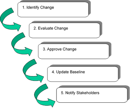
Figure 59. Approach for Change Identification
1. Identify Change
The primary aspects of change identification are:
- Who can suggest a change?
- How is the change request documented?
Each architecture effort will need to make a decision about who can initiate a change request. In some areas the selected answer will be "anyone". Allowing anyone to initiate a change is conducive to the development of a "consensus" architecture because it empowers all stakeholders to provide inputs. However the approach does have a drawback – if literally anyone can input requests the region runs the risk of being overrun by requests that will tax scarce resources to review and decide upon proposed changes. An alternative approach that may be attractive to some larger regions is to limit who can make change requests to members of the maintenance committee/board or members of other key ITS committees. This effectively means that any change suggested has the approval of a key stakeholder. This approach is planned in the Northeastern Illinois maintenance plan. This has the added benefit of spreading the resources needed to generate or evaluate changes among the group.
It is recommended that a simple change request form be created that contains at least the following information (note something like this is relevant for any maintenance approach):
- Name of change
- Description of change
- Rationale for change
- Originator name or agency
- Originator contact information
- Date of origination
As part of the configuration management process this information should be maintained in a change log (or change database) that would add the following additional fields of information:
- Change number (some unique identifier)
- Change disposition (accepted, rejected, deferred)
- Change type (minor or significant)
- Part of baseline affected (could be check boxes for document, database, web site, and not known)
- Disposition comment
- Disposition date
There are many ways the above change forms can be implemented. The form
could be on a regional architecture website for download by anyone submitting a
change. A less formal alternative would be for a change request to be submitted
as an email containing the key information above. The formality in the process
creates an audit trail of all changes considered as well as a record of those
approved, those rejected, and those deferred. This audit trail can come in
handy in future assessments of proposed enhancements or changes to the systems.
The above description of initiating changes applies to individual change suggestions that might arise from review of the architecture by a stakeholder or from the impact of individual projects. In the case of a full baseline update of the regional ITS architecture, this could be handled by a summary change request indicating the nature of the update and referencing the stakeholder interactions that will generate a set of changes.
2. Evaluate Change
When using the incremental change approach to maintenance, each change request needs to be evaluated to determine what impact it has upon the architecture baseline. This evaluation could be required of the person proposing the change, or it could be performed by someone else (possibly the person, or group of people responsible for maintaining the architecture). Since a proper evaluation of a change requires detailed knowledge of the aspects of the regional ITS architecture baseline that are affected: it is usually a better idea to have someone on the maintenance committee (or their staff) do the evaluation. If the proposal for architecture modification has an impact on other stakeholders, someone from the maintenance committee should contact the stakeholders to confirm their agreement with the modification. If the issue warrants it, a stakeholders meeting or teleconference to discuss the modification may be held. In the case of a full baseline update, the change evaluation happens through stakeholder consensus as part of the overall update.
3. Approve Change
When using the incremental change approach, the changes should be presented to the maintenance committee along with recommendations to approve, defer, or reject them. This could be handled informally through email, or through periodic face-to-face meetings.
The maintenance plan should identify how change approval will occur and any procedures that will be used to make the decisions. For instance:
- Should approval require unanimous consensus of all members of the committee?
- Approval of all stakeholders affected by the change?
- Or just a majority of the committee members?
The procedure used depends greatly on the nature of consensus building in the region. Approval of affected stakeholders is a good approach and one that may fit a wide range of conditions. For example, if a change to an interconnection between the traffic management center and the transit center is suggested, then approval by the appropriate traffic and transit agency represents consensus on the change and should be all that is needed for approval. Unanimous consent is not recommended as it is the hardest to maintain (and may slow down the process considerably due to trying to get all parties to respond, or come to meetings). In the case of full baseline update, the approval comes from the stakeholder inputs obtained when each architecture input is revised.
4. Update Baseline
This activity involves putting the changes into the architecture baseline documents, web files, and databases. This requires much the same skills and techniques used in creating the initial baseline. When using the incremental change approach, all the changes would be entered by one or more assigned personnel, and then checked per the process described in the maintenance plan. When using the full baseline update, new versions of documents, web files, and databases would be circulated to stakeholders for a wider review. In addition, the change log would be updated to describe the actual change made and the version identification of all architecture baseline material would be updated as described in the maintenance plan. In some cases, the changes might be held until there is sufficient volume to make the changes efficiently.
5. Notify Stakeholders
The final part of the maintenance process is to notify stakeholder of the changes or updates to the architecture. This applies equally to incremental change and full baseline update approaches. In order to perform this notification, the maintaining organization should create and keep up to date a contact list for all stakeholders represented in the architecture. As part of the maintenance process, this contact list should be reviewed and updated periodically to identify changes in personnel or changes in contact information (e.g. phone numbers or email addresses).
The task of actually notifying the stakeholders of changes may be handled in a variety of ways ranging from hard copy to e-mail to websites. Each approach has its strengths and weaknesses, and what is best for the region will be based on the current methods of communicating. A suggested approach that may meet a wide range of needs is to identify a website where information about the architecture is available and have a place on that website to provide notification of changes. This could be coupled with email notification to the stakeholder list that a change has occurred and to access the information on the website. As part of the note, as well as on the website, it would be good to provide the new version and date of baseline items along with a short summary of the changes.
4.7.3.2 Configuration Identification
Each configuration item must have a unique identifier associated with it. The identifier for the item should be marked on it in some fashion, so that the item can be identified without error and tracked. In the context of regional ITS architecture maintenance, this can be accomplished by suffixing a version number and date in the file name for a database file or electronic document, or it can be physically marked on a printed document. The identifier can also be included in a header or footer for documents and diagrams. In this way, everyone who reads the materials or looks at the database (using RAD-IT, for example) will know which version they are reviewing.
It also makes sense to have a controlled document that lists all of the configuration items and the versions that constitute that baseline in time. Maintenance history can also be included. Any interdependencies between the items are worth recording. There are several reasons for this:
1. You want to be able to know what items you have under configuration control and be able to locate them. Marking them with a unique identifier makes it possible to do that.
2. You want to be able to track the status of each item as it changes.
3. If a change is made to one of your configuration items, you want to be able to determine the impact of that change on the other items.
4.7.3.3 Configuration Control
Configuration control refers to the process of identifying, evaluating and approving changes (as laid out in the Architecture Maintenance Plan) and then updating the baseline and all associated documentation. Any additions after the initial release of that baseline will be noted with a changed version number and date to the relevant identifiers. This must also include an update and new version of the overall configuration item list that documents the current versions of all configuration items.
In the case of a regional ITS architecture the baseline consists of databases, documents, and possibly other supporting outputs such as spreadsheets or drawing files. The process of configuration control and of updating these can become challenging since there is likely to be more than a single representation of the same information. For example, if a RAD-IT database contains the architecture inventory and an architecture document contains a table that lists this inventory, these two representations of the same information need to be kept in sync. Eliminating this kind of duplication is not really an option because a database representation of the architecture is needed to manage the large number of elements and connections, but some form of documentation is also required to make the information more understandable and usable for the stakeholders. The solution is to be aware of the duplication and to put in place a plan to manage it. Because of the potential for changes affecting multiple parts of the baseline, the changes in each part of the baseline should be coordinated with updates in other parts of the baseline. This is particularly true when using the incremental change approach to architecture maintenance.
4.7.3.4 Configuration Status Accounting
Configuration status accounting is the process of ensuring that all of the relevant information about an item – documentation and change history – is up to date and as detailed as necessary. This includes the status of all pending changes. A primary goal of configuration status accounting is to disseminate configuration item information necessary to support existing and future change control efforts. A typical configuration status accounting system involves establishing and maintaining documentation for the entire life cycle of an item. Status accounting is ideally carried out in conjunction with change control.
The primary benefit of configuration status accounting is that it provides a methodology for updating all relevant documentation to ensure that the most current configuration is reflected in the configuration identification database. It accounts for the current status of all proposed and approved changes. The goal is to provide decision makers with the most up-to-date information possible. Having the most recent information about a change item or including how the changes were implemented helps reduce research efforts in the future whether implementing a new change or rolling back a change that had a negative or unexpected impact.
For a regional ITS architecture, the primary configuration items might be a document and a RAD-IT database. Report the status on these items periodically to interested stakeholders just to let them know that these files are still the latest. This can be done during regular stakeholder meetings, e.g. an ITS Committee meeting.
When using the incremental change approach, the other thing typically reported would be the list of pending changes to the regional ITS architecture, and for a small region there may not be very many changes typically encountered and these may be very infrequent. So, in addition to identifying the latest version of the architecture, the region might report that there have been 2 changes received from stakeholder A and B that these haven't been implemented yet but are expected to be worked on in the next 6 months. When using a full baseline update approach pending changes are collected but probably not reported until summarized in the change log that occurs when the full baseline is updated.
4.7.3.5 Configuration Audits
In the general discipline of configuration management, configuration verification and audit is the process of analyzing configuration items and their respective documentation to ensure that the documentation reflects the current situation. In the case of a regional ITS architecture the configuration items are the documentation. Hence this step in the process becomes a rather simple one that can look at two aspects of the architecture:
- Verifying the correctness of the configuration status accounting report
- Verifying that different representations of the architecture information, e.g. the RAD-IT file and the document, are in sync
This type of audit is most applicable when using the incremental change approach, which may result in many small updates to configuration items, but is also a good idea to perform at the end of the effort in the full baseline update. Issues and changes are then provided as feedback to the maintainers of the architecture.
5 Regional ITS Architecture Use
The implementation of transportation projects can be seen as a lifecycle as shown below and the regional ITS architecture can be used to support the planning, programming, and implementation of those projects, as described in this section.
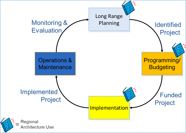
Figure 60. Regional ITS Architecture Usage in the Transportation Lifecycle
The diagram above shows the transportation project lifecycle at the highest level. Starting at the top of the diagram, goals and objectives of the transportation system are identified in long-range planning. To meet these goals and objectives, strategies and projects to implement the strategies are identified. To deploy the projects, funding must be secured via the federal transportation programming and/or agency budgeting processes. Once funding has been secured for a project, it can be implemented. Once implemented, it is operated and maintained (O&M). During O&M ideas for improvement or replacement are identified and fed into the long-range planning process to begin the cycle again.
The regional ITS architecture supports three of these major steps – planning, programming, and implementation.
1. Use in Long Range Transportation Planning. A regional ITS architecture can be used to support metropolitan and statewide long-range transportation planning. A regional architecture provides a means by which peer agencies can jointly define their vision for ITS development based on regional goals and objectives. Using the regional ITS architecture, a region can plan for technology application and integration to support more effective planning for operations.
2. Use in Programming/ Budgeting. A regional ITS architecture can be used to support the programming/ budgeting of projects in metropolitan and statewide regions. The regional ITS architecture provides a high-level description of ITS projects, which can serve as an input the definition and prioritization that occurs during programming/ budgeting.
3. Use in Project Development. By starting with the regional ITS architecture, the steps taken by each project will be on the path to fulfilling the broader objectives set forth in the long-range transportation plan. A well-maintained regional architecture that is created and maintained using RAD-IT provides context for ITS projects and the initial input for the systems engineering for a project. Once a project has been articulated in RAD-IT, the systems engineer can use SET-IT to develop project specific output. Project-relevant information from RAD-IT can be used within SET-IT to support not only the development of a project architecture, but also the systems engineering documentation such as Concept of Operations and System Architecture Document.
5.1 Use in Long Range Transportation Planning
This page provides a guide for using a regional ITS architecture as part of long-range transportation planning. Due to regional and local variations in the practice of transportation planning, this guide represents a wide range of options available to each state, region, or agency rather than a single recommendation. There is no need to fundamentally change the planning processes in the region to use the architecture. The regional ITS architecture is a tool that can be used to support planning for ITS within the context of existing transportation planning processes. Local stakeholders must decide how best to incorporate the regional ITS architecture and the products produced during its development into their transportation planning process.
The goal of the planning process is to make quality, informed decisions pertaining to the investment of public funds for regional transportation systems and services. Using the regional ITS architecture to support these planning activities is an important step in the mainstreaming of ITS into the traditional decision-making of planners and other transportation professionals. As shown in the section on Architecture Update, transportation plans and programs are important inputs to the development of a regional ITS architecture. Once an architecture is complete, it can feed detailed ITS-specific information back into the planning process.
Adapted from "An Objectives-Driven, Performance-Based Approach to Planning for Operations" from FHWA's Advancing Metropolitan Planning for Operations: The Building Blocks of a Model Transportation Plan Incorporating Operations - A Desk Reference, (FHWA-HOP-10-027, https://ops.fhwa.dot.gov/), the figure below shows the key steps in the transportation planning process for Federal-aid projects. This process is focused on Management and Operations, which are the aspects of planning that most relate to ITS systems and ITS deployments. These steps will be elaborated on in following sections.
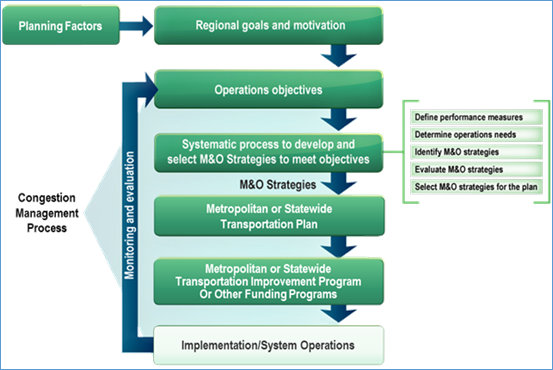
Figure 61. An Objectives-Driven, Performance-Based Approach to Planning for Operations
The transportation planning process is driven by a regional vision and set of goals. These drive transportation improvement strategies that are a mix of capital improvements and operational improvements. The planning organizations evaluate and prioritize the various strategies, and the resulting output is a document called the Long-Range Transportation Plan (or sometimes Metropolitan Transportation Plan or Statewide Transportation Plan). This plan is the key output of long-range planning. The Long-Range Transportation Plan feeds the Programming function which produces the Transportation Improvement Program (TIP). Once a project is programmed then project development can begin All of these steps occur with a variety of critical factors and inputs as shown in the figure. While this process is for Federal-aid funded projects, typically agency planning follows similar steps.
Select the steps in the objectives-driven, performance-based approach to planning for operations (in the diagram above) to explore sample planning outputs and their connection to the ITS Architecture.
5.1.1 Architecture & Long Range Planning
How can a Regional ITS Architecture support the long-range transportation planning process? In the following basic ways that will be expanded upon below:
- The services described in the Regional ITS Architecture can be related to the operational objectives or operational strategies that can be used to improve the transportation system to meet the region's vision and goals.
- The definition of an integrated transportation system described by the Regional ITS Architecture can support the operations and management element of the transportation plan.
- The process of developing and maintaining a Regional ITS Architecture can help to enhance the linkage between operations and planning through closer involvement of a wider array of stakeholders from both of these areas of transportation.
One of the first steps in using a regional ITS architecture to support transportation planning is to determine the regional ITS architecture(s) that apply to the planning area. In most cases, there is a single architecture that corresponds to the state or metropolitan planning area and the choice is obvious. In a few areas around the country, more than one regional ITS architecture may apply. Where more than one architecture applies, it is important to understand the relationship between each architecture and the transportation planning process, which should be included in the architecture use section of each regional ITS architecture. See Architecture Scope for more information on defining architecture scope.
5.1.2 Goals, Objectives, and Strategies
The planning process usually begins with a regional vision and goals. These goals are often very high-level statements such as "preserve the multimodal transportation system" or "enhance public safety and security", which happen to be two of the six goals in the California Transportation Plan 2040.

Figure 62. Operational Strategies to Support Regional Goals and Objectives
These high-level goals are then further defined as objectives, recommendations, or strategies. As shown in the figure above, some of the strategies involve operational or capital improvements. ITS is typically focused on Operations solutions. These operations solutions include asset or access management, traffic signal timing, congestion mitigation, corridor management, emergency traffic operations, incident and freeway management, freight operations, traveler information, road weather solutions, tolling and road pricing programs, demand management, and work zone management.
The Regional ITS Architecture can provide an array of potential operational improvements through the services that are defined in it.
As an example, the following recommendation (supporting the goal of preserving the transportation system) is contained in the California Transportation Plan 2040:
Use research, technology, innovative techniques, and new materials to extend the life of the multimodal system, and to monitor defects so they can be addressed cost-effectively without risk to public safety. Utilize and install new operational strategies and technologies to optimize system capacity.
This recommendation can be addressed by several of the services contained in the California statewide ITS architecture, including work zone management, traffic information dissemination, broadcast traveler information, travel demand management, and interactive traveler information. Additional examples of strategies with their roots in the Regional ITS Architecture can be found in other LRPs and overall this represents one way for the Regional ITS Architecture to be used in the planning process.
Strategies that have traditional transportation technology projects as their primary solution may add ITS elements or services as a part of the overall strategy solution. For example, to reduce congestion, a corridor is planned for widening. This project could also include incorporation of ITS elements and services to better manage the upgraded corridor.
The selection of services to support strategies will be simplified for the planning organization if the Regional ITS Architecture has the Regional Goals, Objectives, and Strategies component that provides mapping from these planning attributes to the more detailed services of the architecture.
Once transportation planners select a set of strategies, they use a variety of tools to evaluate the various strategies for transportation improvement. One aspect of the evaluation of strategies is to understand their impact on the transportation network. This may be done via collection of transportation data and the development of performance measures relating to the network. The Regional ITS architecture can provide an overview of the current data collection or performance monitoring capabilities of the region (through the Data Management services defined in the architecture). Through the projects defined in the architecture, plans for expansion of data collection capabilities are also defined. Review of this information in the architecture by planners can highlight these data collection or performance monitoring capabilities, pointing the planners to possible sources of data or performance monitoring that might assist them in the evaluation of the strategies.
As an example of the connection between projects and planning, the Minnesota Statewide ITS Architecture has a detailed mapping within the description of each project to the transportation plan objectives, as well as to the Transportation Systems Management and Operations (TSMO) objectives.

Figure 63. Project Initiative from Minnesota Statewide Architecture
In this example from the Minnesota Statewide ITS Architecture (2018 update, available at https://www.dot.state.mn.us/its/projects/2016-2020/itsarchitecture.html) each project or, in this case, initiative, lists various information about that project including the description, costs, ties back to the architecture, and as shown here, ties to the Needs and ITS Objectives that had been previously identified. Here we see that this initiative for the "Real-Time Integration of Arrow Board Messages into Traveler Information Systems" is tied to objectives to support things like reducing the total vehicle hours of delay caused by work zones. Each project or initiative is also related to a TSMO Goal or one or more TSMO Objectives.
5.1.3 Long Range Plan
In the traditional transportation planning process, the Long-Range Plan is the output product of the process for long-range planning. Across the country, this plan is called various names including Regional Transportation Plan (RTP), Long-Range Transportation Plan (LRTP) or just Long-Range Plan (LRP). In this discussion it will be referred to as the "Long-Range Plan", "The Plan", or LRP.
The Plan documents the policy direction for the region and describes how transportation projects and programs will be implemented over a 20-year (or longer) period. It must be updated periodically by each state and metropolitan area. The Long-Range Plan is the expression of a state or metropolitan area's long-range approach to constructing, operating, and maintaining the multimodal transportation system. It is the policy forum for balancing transportation investments among modes, geographic areas, and institutions.
The requirements for metropolitan transportation planning are defined in Title 23 U.S.C. Sec. 134. In that federal code, seven planning factors are defined. One of the key ones, in the context of the regional ITS architecture is to "promote efficient system management and operation". The recent transportation bill, MAP-21, the Moving Ahead for Progress in the 21st Century Act (P.L. 112-141) added the following words to the portion of Section 134 which describes what needs to be included in a transportation Plan: "Operational and management strategies to improve the performance of existing transportation facilities to relieve vehicular congestion and maximize the safety and mobility of people and goods." One of the key purposes of a Regional ITS Architecture is to provide a technical plan for improving integration of elements of the transportation system in order to address operational and management strategies as defined in the transportation plan.
A second Section of the Code, 135, applies to statewide planning and in this section the following similar requirement has been added: "The statewide transportation plan and the transportation improvement program developed for each State shall provide for the development and integrated management and operation of transportation systems and facilities."
Due to these revised requirements, operations and management will be considered in all both metropolitan and statewide transportation plans as they are revised in the future. Many existing plans already have explicit sections relating to operations and management. An example of this type of inclusion is taken from the 2040 Metro Vision Regional Transportation Plan (for the Denver metropolitan region): Under the System Management and Operational Improvements element they have the following: "System management and operations improvements and actions are largely supported and enabled by intelligent transportation systems (ITS) – technology tools and systems that facilitate and implement desired operations and processes." This makes a direct connection between the plan and the ITS systems being deployed. In other plans the direct connection is provided by defining strategies that specifically address technology. For example, the North Jersey Transportation Planning Authority (NJTPA) Regional Transportation Plan includes the following strategy: "Use technology to improve transportation operations"
Some transportation plans make explicit reference to the Regional ITS Architecture. For example, the NJTPA plan mentioned above includes the following investment guideline: "Invest in technological improvements in accordance with the region's Intelligent Transportation System (ITS) architecture." Some other plans include directly executive summary information from the region's architecture as part of the plan. The level at which each region connects their transportation plan to the region's architecture is a regional choice, but the following actions taken during the update of the regional ITS architecture can facilitate the connection between these two planning activities:
1. Creating an executive summary, including graphics that present the integration opportunities identified in the architecture in an accessible way. These can be included directly or in part into the transportation plan in support of the section of the plan which deal with operations and management.
2. Make sure that the regional goals, strategies, and objectives are tied to the regional ITS architecture (as described in the architecture component discussion on Goals, Strategies, and Objectives). This will facilitate the connection between components of the architecture (e.g. services) and the planning attributes around which the transportation plan is focused.
3. Consider formally adopting the Regional ITS architecture, which can have several benefits. Formal adoption adds credibility to the Regional ITS Architecture, allowing planners to use aspects of the architecture with the knowledge that the region has agreed to the architecture. Formal adoption also encourages additional rigor in the architecture maintenance process. There may be situations where this suggestion will not be practical due to institutional complexities or due to the ITS architecture having a distinctly different (e.g. larger) geographic scope than the regional planning organization.
4. Ensure that transportation planners are included in the stakeholder discussions for all updates of the architecture. Having planners and operations staff work together on the updates will help the planners understand the range of regional operations and management efforts planned and will lead to the planners having a better knowledge of how to find information relevant to them in the architecture outputs.
5.1.3.1 Transportation Planning Factors
Under the Intermodal Surface Transportation
Efficiency Act of 1991 (ISTEA) and the Transportation Equity Act for the 21st
Century of 1998 (TEA-21), Congress showed support for metropolitan and
statewide transportation planning by emphasizing seven distinct planning
factors that metropolitan planning organizations (MPOs) and states should
consider when developing their plans. In 2005, the Safe, Accountable, Flexible,
Efficient Transportation Equity Act: A Legacy for Users (SAFETEA-LU), added
emphasis in two areas: security and the environment. Transportation security
was made a stand-alone factor, increasing the total number of factors to eight
and signaling an increase in importance from prior legislation. The factor
relating to the environment was also expanded, to promote consistency of the
long-range transportation plan with planned growth and development. The most
recent authorization, Fixing America's Surface Transportation (FAST) added two
planning factors for: 1) System resiliency and reliability, and 2) Travel and
tourism.
Per the legislation, the planning factors must
be considered in the implementation of projects and strategies and services. A
representative set of goals that have one to one correspondence with the
planning factors are also included in the table.
Table 5. Planning Factors to Goals
|
Planning Factor |
Goal |
|
A. Support the economic vitality of the United States, the States, nonmetropolitan areas, and metropolitan areas, especially by enabling global competitiveness, productivity, and efficiency; |
|
|
B. Increase the safety of the transportation system for motorized and nonmotorized users; |
Achieve a significant reduction in traffic fatalities and serious injuries on all public roads |
|
C. Increase the security of the transportation system for motorized and nonmotorized users; |
|
|
D. Increase the accessibility and mobility of people and for freight; |
|
|
E. Protect and enhance the environment, promote energy conservation, improve the quality of life, and promote consistency between transportation improvements and State and local planned growth and economic development patterns; |
|
|
F. Enhance the integration and connectivity of the transportation system, across and between modes throughout the State, for people and freight; |
Enhance the integration and connectivity of the transportation system |
|
G. Promote efficient system management and operation; |
|
|
H. Emphasize the preservation of the existing transportation system; |
Maintain the highway infrastructure asset system in a state of good repair |
|
I. Improve the resiliency and reliability of the transportation system and reduce or mitigate stormwater impacts of surface transportation; |
Improve the resiliency and reliability of the surface transportation system |
|
J. Enhance travel and tourism. |
Develop a transportation system that supports travel and tourism |
Architecture Use
Intelligent transportation systems support each of the planning factors to some degree. Factor F, which focuses on integration and connectivity of the transportation system, is of particular interest since integration is a principal motivation for a regional ITS architecture. Using and maintaining a regional ITS architecture is a key tool for achieving this planning factor. The other factors are addressed by specific ITS services that achieve the identified benefits. Select the goals associated with each planning factor to see the objectives, performance measures, and service packages that support each planning factor.
5.1.3.2 Regional Goals
Transportation planning and investment decisions are based on the public's desired outcomes for the transportation system. Transportation planning begins with a set of broad goals that reflect the desired outcomes and the transportation vision for the region. The goals identified in the table below are representative of the goals that are included in metropolitan and statewide transportation plans. As shown in the table, the representative goals included in the Architecture Reference for Cooperative and Intelligent Transportation (ARC-IT) are closely tied to the planning factors required by 23 CFR 450 . Select any of the goals to traverse to more specific objectives that support the goals, performance measures that can be used to measure the progress towards the objectives, and ultimately the service packages in ARC-IT that support each objective.
Table 6. Goals to Planning Factors
|
Goal |
Planning Factor |
|
A. Support the economic vitality of the United States, the States, nonmetropolitan areas, and metropolitan areas, especially by enabling global competitiveness, productivity, and efficiency; |
|
|
Achieve a significant reduction in traffic fatalities and serious injuries on all public roads
|
B. Increase the safety of the transportation system for motorized and nonmotorized users; |
|
Improve the security of the transportation system
|
C. Increase the security of the transportation system for motorized and nonmotorized users; |
|
D. Increase the accessibility and mobility of people and for freight; |
|
|
E. Protect and enhance the environment, promote energy conservation, improve the quality of life, and promote consistency between transportation improvements and State and local planned growth and economic development patterns; |
|
|
Enhance the integration and connectivity of the transportation system
|
F. Enhance the integration and connectivity of the transportation system, across and between modes throughout the State, for people and freight; |
|
Improve the efficiency of the surface transportation system
|
G. Promote efficient system management and operation; |
|
Maintain the highway infrastructure asset system in a state of good repair
|
H. Emphasize the preservation of the existing transportation system; |
|
Improve the resiliency and reliability of the surface transportation system |
I. Improve the resiliency and reliability of the transportation system and reduce or mitigate stormwater impacts of surface transportation; |
|
Develop a transportation system that supports travel and tourism |
J. Enhance travel and tourism. |
Each goal above is linked to a set of Objectives which are, in turn, tied to associated performance measures and service packages. Consult the ARC-IT website to see these connections.
Architecture Use
The regional ITS architecture must be consistent with the goals established in the relevant transportation plan(s) to facilitate use of the architecture in transportation planning. When this connection is established, the regional ITS architecture can help regions realize their goals by defining the integrated framework for ITS components that support the goals. If your regional ITS architecture does not include this connection, the links between the representative goals and ARC-IT defined in this planning view may be used as a starting point.
5.1.3.3 Objectives
Each of the goals in a metropolitan or statewide transportation plan is supported by one or more 'objectives' that define what needs to occur to accomplish the goals. The objectives define what a region plans to achieve and help to determine the strategies and investments that will be included in the transportation plan. In practice, objectives range from high-level regional statements down to Specific, Measurable, Achievable, Realistic, and Time-bound (SMART) objectives. A range of objectives are included in the Architecture Reference for Cooperative and Intelligent Transportation (ARC-IT), gathered from a variety of references and recent transportation plans, that reflect the spectrum of objectives that are used in current practice. Select an objective to identify its source, associated performance measures, and the service packages in ARC-IT that support the objective.
Architecture Use
Like the goals, the transportation objectives of the region should be a driving input for the regional ITS architecture. By connecting the objectives with the architecture, transportation planners can easily identify the portion of the integrated regional transportation system that supports each objective. Conversely, ITS architectures and strategic plans can help planning organizations define operations objectives that reflect data that is available and the expertise of operations staff. The RAD-IT Planning Tab can be used to connect your region's objectives with your regional ITS architecture. If your regional ITS architecture does not include this connection, the links between the objectives and ARC-IT defined in this planning view may be used as a starting point.
The objectives have been mapped to associated performance measures and service packages. Consult the ARC-IT website to see these connections.
5.1.4 Planning for Operations (including TSM&O)
Starting with MAP-21, the FHWA and FTA increased their emphasis on "the use of an objectives-driven, performance-based approach to planning for operations as an effective way to integrate operations into planning and programming."
From the FHWA web page on Integrating Operations into Planning and Programming:
This approach focuses on both short-term and long-term system performance, using established system performance measures rather than simply focusing on implementation of projects as a measure of success. It can be applied to both metropolitan and statewide transportation planning processes. The approach emphasizes consensus and collaboration across modes and jurisdictions and between planners and operators to help ensure that regional transportation investment decisions reflect the consideration of available strategies and approaches to meet a region's transportation goals and objectives.
An objectives-driven, performance-based approach to planning for operations is based on the concept that "what gets measured gets managed." Investments are made with a focus on their contribution to meeting regionally agreed-upon objectives. By implementing this approach, resources are allocated more effectively to meet performance objectives, resulting in improved transportation system performance.
The key output that regions are currently creating to describe the integration of Planning and Operations is a Transportation Systems Management and Operations (TSMO) Plan. TSMO is defined in MAP-21 SECTION 1103 (a) (30) (A) as "An integrated set of strategies to optimize the performance of existing infrastructure through the implementation of multimodal and intermodal, cross-jurisdictional systems, services, and projects designed to preserve capacity and improve security, safety, and reliability of the transportation system."
A TSMO plan considers the integration of planning and operations through three elements:
- Strategic – such as the business case for TSMO, vision and program mission, goals and performance objectives
- Programmatic – such as leadership and organizational structure, staffing and workforce needs, business processes
- Tactical – such as TSMO projects and services, implementation policies
A TSMO plan describes a set of strategies that revolve around these three elements. The connection with ITS is through the tactical element, which can define operational improvements that can maintain and even restore the performance of the existing transportation system before extra capacity is needed.
FHWA has developed a set of example strategies to address the tactical element that strongly embrace ITS services. The example strategies include:
- Work Zone Management
- Traffic Incident Management
- Special Event Management
- Road Weather Management
- Transit Management
- Freight Management
- Traffic Signal Coordination
- Traveler Information
- Ramp Management
- Congestion Pricing
- Active Transportation and Demand Management
- Integrated Corridor Management
- Access Management (this may not involve ITS but may involve Operations)
- Improved Bicycle and Pedestrian Crossings
- Connected and Automated Vehicle Deployment
The Regional ITS Architecture can provide relevant inputs to the development of a TSMO plan. The primary goal of a Regional ITS Architecture is to create a plan focused on regional integration to improve the safety and efficiency of the transportation system. The definition of ITS projects and ITS services in the architecture can be used as a basis for strategies defined in the TSMO plan.
ITS Projects define not only short-range efforts, but also medium and long-range projects. The architecture addresses projects for a wide range of stakeholders, consistent with the TSMO goal of creating a set of projects that are "multimodal and intermodal with cross-jurisdictional systems, services, and projects".
5.1.5 ITS Strategic Plans
An ITS Strategic Plan (sometimes known as an ITS Strategic Assessment, ITS Deployment Plan, etc.) is a guide for implementation of ITS in a region. These plans may be developed in conjunction with a regional ITS architecture update, or may be the product of separate efforts. In the former case, the ITS Strategic Plan may be one of several documents produced during the architecture update. In some cases, the regional ITS architecture is just a part of a larger effort and the architecture may represent a portion of the overall ITS Strategic Plan documentation. In more recent examples where the ITS Strategic Plan was created via a separate effort, the regional ITS architecture used to guide development of the plan and is referenced in the plan. The figure below shows that in whatever form or relationship exists between the architecture and the ITS strategic plan, these efforts can be used to support both the LRP and the Transportation Improvement Program which is covered in page on Architecture Use in Programming/Budgeting.

Figure 64. ITS Architecture and ITS Strategic Plans
Why have regions created ITS Strategic Plans? There is no Federal requirement for an ITS Strategic Plan, but many regions have found this a useful way to define their ITS needs and identify what capabilities to best meet the needs and provide this as input to the formal planning process. Regions have used this plan as a bridge between the regional ITS architecture and the strategies and project transportation planning process. In some ways an architecture is detailed but compared to a Strategic Plan and the documents of the planning process it is not – as it doesn't usually define location-specific projects.
Often the ITS Strategic Plan includes several of the architecture outputs. The most common architecture outputs contained in the plans are the Project Sequencing and the List of Agreements.
What distinguishes these plans is that they usually contain details and data that go beyond the architecture components. For instance, a strategic plan may define where the ITS services will be deployed so specific projects can be identified.
Some of the typical components that are often included in ITS Strategic Plans include:
- ITS Vision: This short statement of why the region is deploying ITS can serve as a tie-in to the larger transportation vision that is articulated in the Long-Range Plan.
- Needs, Goals, and Objectives addressed by ITS: Defining the needs, goals, or objectives (or in some areas policies) that ITS will address provides a direct connection to the needs, goals, or objectives that are the basis of the Long-Range Plan. Tying the ITS deployments to larger transportation issues of the region is an excellent way to inject ITS projects into the regional planning process.
- Strategies for ITS deployment: Transportation planning tends to articulate "strategies" for regional transportation. The Regional ITS Architecture as described in the previous sections tends to have specific elements, services, information exchanges and projects as its outputs. What is missing in the usual list of architecture outputs is a strategy for how and where (what locations) ITS will be deployed over time. Many regions add this to their ITS Strategic Plans.
- Funding considerations: Funding sources and funding requirements for ITS deployments may be considered. In order to make these funding assessments, some deployment considerations must be evaluated. Issues of funding system operations and maintenance are especially important to ITS deployments, and consideration of this topic may be included.
- Detailed project definitions: The regional ITS architecture may identify general regional projects that are then defined with additional specificity in the strategic plan. For example, a single general surveillance project for a metropolitan area may be split into several phased projects that add instrumentation to different parts of the metropolitan area over time. The location-specific projects may be defined so they are coordinated with other planned capital improvements or simply to stage the implementation so the highest-priority locations are instrumented first as funds become available. The more detailed location-specific project definitions are required to support accurate cost estimates.
- Gaps in planned projects: The Regional ITS Architecture suggests elements, services, and information exchanges that will be implemented over the timeframe selected for the architecture. The projects listed in the architecture invariably implement only a subset of the parts of the architecture. Identification of the "gaps" between the project list and the architecture, along with a prioritization of the gaps can result in a very useful understanding of where additional projects might be needed to address needs.
- Benefits Analysis: Since transportation projects are ultimately "scored" with some factoring of cost/benefit as the projects move to the programming stage, having a discussion of the benefits that accrue from ITS projects can assist in understanding the benefit part of the cost/ benefit equation for these projects. This discussion of cost/ benefits could be a part of the Project Sequencing output or a part of a Strategic Plan, depending on the approach taken by the region.
- Communications Plan: The architecture focuses on transportation services, but the supporting communications infrastructure to support these services is critical to the successful implementation of ITS projects. Consequently, some regions will create communications plans as part of their strategic plans to identify the issues, strategies, and regional solutions surrounding this important aspect of ITS deployments.
The common thread in the topics given above is the desire to better connect ITS deployments (as described in the regional ITS architecture) to the transportation planning process (as described by the LRP). The Strategic Plan focuses on Management and Operations strategies (because that is the primary focus of ITS services), which are a required aspect of the LRP.
Regions should consider the
content and organization of their LRP and develop an explicit connection
between the goals, objectives, or policies of the LRP and the regional ITS
architecture. This may involve going beyond the basic architecture content to
include one or more of the topics listed above but it will allow a clearer
connection between the architecture and the planning process.
Whether this takes the form
of a separate ITS Strategic Plan or is contained in architecture documentation
is entirely at the discretion of the region. One reason to encourage in
inclusion of a Strategic Plan is the ability to identify and discuss the
locations for deployment of the ITS services and strategies across the region.
5.2 Use in Programming/ Budgeting
Regional and statewide programming and agency capital planning (a.k.a. budgeting) involve identifying and prioritizing ITS projects. The result is funded projects.
Using a regional ITS architecture to define an ITS project links the objectives and strategies of the region, which are referenced in the architecture with the ITS deployed in the field. In a region, ITS projects are deployed by many organizations including the State Department of Transportation, transit agencies and many local agencies and authorities. The regional ITS architecture provides a common reference point for projects deployed by various organizations allowing improved coordination between agencies as they implement projects that integrate systems within the region.
ITS projects in a region may be funded by a variety of sources. ITS projects that are funded with federal funds are programmed by Metropolitan Planning Organizations (MPOs) and State DOTs with input from transportation agencies in the region. All organizations in a region, whether they use federal funds to deploy ITS or not, perform short term planning via their capital planning (i.e. budgeting) process.
5.2.1 Architecture Use in Programming Federal Funds:
The Transportation Improvement Program (TIP) is a staged, multiyear, intermodal program of transportation projects that is consistent with the long range transportation plan for a metropolitan area. At the statewide level there is a corresponding Statewide TIP (STIP) that is consistent with the long range statewide transportation plan. The TIP/STIP assigns federal funding to a prioritized list of specific projects to be constructed over a several-year period (usually three to six years) after the program's approval.
The regional ITS architecture can be used to support definition of ITS projects that are submitted for federal funding. In some regions, ITS projects in the TIP/STIP are not defined in much detail. Sometimes merely a placeholder for ITS projects is included. A benefit to using a regional architecture to define ITS projects is that the projects can be specified in greater detail thereby allowing more realistic estimates of the costs, benefits, schedule, etc.
When
project sponsors submit ITS projects for programming, some planning agencies
require that the sponsors submit architecture-related information about the
project. Some agencies merely require yes/no questions to be answered regarding
the project's inclusion in the regional architecture while others request more
detailed information such as the elements, services, and/or interfaces of the
architecture to be deployed in the project. If an ITS project is submitted
which is not included in or is not consistent with the regional architecture,
the project sponsors can consider how to use the architecture to define
projects, which is discussed in Architecture Use to Identify and Define Projects.
In the TIP/STIP, projects that contain ITS elements should be designated as ITS projects so that projects sponsors are aware of the associated requirements from the federal regulation on architecture.
An example of this is from the San Francisco Bay Area Metropolitan Transportation Commission (MTC). MTC identifies ITS projects in their TIP (within their TIP software system, WEB FMS) as shown below.

Figure 65. Metropolitan Transportation Commission TIP Report
The programming process involves prioritizing projects and using federal funds to fund the top priority projects. Each region has a process for prioritizing projects. The regional ITS architecture can be useful in this process as it reflects the vision for ITS in the region so a factor in prioritization should be how well a project fits within the regional architecture. In some regions, projects (of some categories) are allotted additional points if they include elements or interfaces of the architecture. For example, the North Jersey Transportation Planning Authority (NJTPA) assigns points to projects that enhance their ITS network based on the scale shown in the figure below.
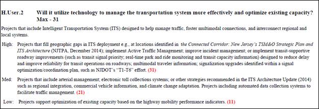
Figure 66. NJTPA ITS Prioritization Criteria
In another example of project prioritization, Maricopa Association of Governments has defined, in their Transportation Programming Guidebook, a set of criteria specifically for ITS projects. In the evaluation there are two key "essential" requirements:
- All projects must be identified on the list of strategies recommended in the Systems Management and Operations Plan (SM&O) Plan.
- All projects must be in compliance with the Regional ITS Architecture.
In addition, the projects are evaluated against criteria such as how well the project meets objectives specific to a SM&O priority category.
A
regional architecture may better support programming if the project sequencing
and related architecture elements are updated on a maintenance schedule that
supports the TIP cycle. The architecture should be updated prior to a project
submittal request so that it can be used by project sponsors to identify
projects. If thorough updates to the architecture are to correspond to LRTP
updates, less major revisions to the architecture can be made to correspond to
the TIP cycle.
5.2.2 Architecture Use in Organization Capital Planning
All agencies including State DOTS, transit agencies, local municipalities, etc. use a budgeting process to allocate funds to projects. A regional ITS architecture should include the existing and planned elements of all stakeholders and how they are or will be interfaced with other ITS elements in the region. Therefore, all organizations can use the architecture to define ITS projects, as defined below, and feed them into their budgeting process.
Many ITS
improvements are implemented as part of larger capital improvement projects. As
traditional capital projects are defined and programmed, it is important to
identify the associated opportunities for efficient ITS implementation. The
regional ITS architecture is a record of the ITS implementation planned by each
agency that can be used to identify these opportunities. Some agencies are
considering policies to review each capital project to determine if ITS
measures should be included before the project moves forward. Many agencies do
this type of review as good practice, but these opportunities would be
identified more consistently and "carry more weight" if this check was formally
defined and required by an established policy. For example, the Albuquerque MPO
is incorporating such reviews to their Plan Development Process that sets the procedures
and steps for administering Federal-Aid projects from project identification
through construction award.
5.2.3 Architecture Use to Identify and Define Projects
A regional ITS architecture includes a sequence of projects as described in Project Sequencing. Projects from the architecture are meant to feed into the programming and/or capital planning processes.
Some agencies and regions have created and used ITS Strategic Plans to define ITS projects. A strategic plan determines the ITS vision of the agency or region and how the vision will be deployed. A strategic plan identifies location-specific projects and the timeframe for deploying them. Typically, an implementation plan for deploying the projects is defined. ITS projects can then be taken directly from the plan and submitted for funding (with Federal or other funds.)
As the projects defined in a regional ITS architecture are sequenced and have defined characteristics (See Project Sequencing for information on defining projects), just as in an ITS strategic plan, organizations can use the architecture to define ITS projects to be submitted for funding from any source. The information contained in a regional ITS architecture can be used to define projects with more detail in order to better scope them and establish project budget requirements. If the project is defined in the regional ITS architecture then the portion of the regional ITS architecture relating to the project can be used.
5.2.3.1 Defining Projects Not in the Architecture
If the project is not currently in the regional ITS architecture, there may still be information in the architecture that can be used to define the ITS project:
- Review the list of stakeholders to identify those that should be involved with the project and those that are or may be impacted.
- Use the stakeholder roles and responsibilities defined in the operational concept to clearly define the roles and responsibilities of the stakeholders involved in the project.
- Review the relevant service(s) (i.e. service package(s)) to identify elements potentially directly or indirectly associated with the project and recognizing potential partners to share development costs, material and/or labor, facilities, etc.
- Use the defined interfaces between ITS elements to identify current and future integration opportunities.
- Utilize the sequence of projects to gain insight into the timetables and other dependencies of a project with others including identifying opportunities to coordinate with capital projects.
- Apply the project description of the project sequencing including any additional information about the project (e.g. costs, benefits, and potential institutional issues) to clearly define the project.
5.3 Use in Project Development
Once an ITS project has been funded and implementation begins, there is a natural tendency to focus on the programmatic and technical details of the project to be implemented and lose sight of the broader regional context for the project. Using the regional ITS architecture as a basis for project implementation provides this regional context. It provides each project sponsor the opportunity to view their project in the context of surrounding systems. It prompts the sponsor to think about how their project fits within the overall transportation vision for the region. It identifies the integration opportunities that should be considered and provides a head start for the systems engineering analysis that is required for ITS projects.
Due
to these potential benefits, the federal Regulation/Policy on Architecture and
Standards requires the regional ITS architecture to be used for project
implementation. Specifically, 23 CFR 940.11.c.1 and FTA National ITS
Architecture Policy Section 6.c.1 require identification of the portion of the
regional ITS architecture that is implemented by each ITS project.
5.3.1 Project Development Approaches
As described in Use for Programming, transportation projects are identified and funded through transportation planning and programming/budgeting phases. Funded projects are then implemented using a project development process that will vary with the type of project.
5.3.1.1 Traditional Project Development Approach
ITS projects that install field equipment, such as the installation of variable message signs, use a process that is very close to the traditional project development process shown in the Figure below. ITS projects that include hardware and software development and integration will require additional systems engineering analyses that can be thought of as extensions to the traditional project development process.

Figure 67. Traditional Project Development Approach
While project development processes vary from state to state and from organization to organization in each state, the transportation project development process tends to have the same major steps.
- Project Initiation – At this step, the project manager is identified, the project team is assembled, and the project development is planned. A high-level definition of the project is developed, costs are estimated, and the required forms and checklists are completed to garner approval for the project from the sponsoring and funding agency(ies). For FHWA and FTA, this is a critical point in the process where approval to proceed is given and federal funds are obligated. For the project sponsor, this is the best opportunity to consider integration opportunities and use the regional ITS architecture to inform the initial project scoping and definition. The regional ITS architecture can be used to define the project's scope at this step – identifying the involved stakeholders and high-level roles and responsibilities, the portion of the regional ITS architecture to be implemented, and where in the project sequencing the project is identified.
- Preliminary Engineering – In the traditional capital project development process, environmental, right-of-way, and other studies are performed depending on the type of project. These studies result in better understanding of the project requirements and constraints. ITS projects that include a construction component will require these same studies as well as additional engineering analyses to fully specify the project requirements for the ITS portion of the project. The regional ITS architecture can contribute to these preliminary engineering analyses since it includes high-level functional requirements and interface definitions that can be used as a starting point. Note that from a federal aid perspective, "preliminary engineering" also includes PS&E. PS&E is split out separately here to differentiate between requirements and design steps in the traditional development process.
- Plans, Specifications, and Estimates – The detailed design for the project, complete with detailed project specifications, estimates of material needs, and associated costs are documented. In a traditional construction project, this process step provides companies with all the information they need to develop an accurate bid. Construction elements within an ITS project will also require traditional design documentation (i.e., layout sheets, plan and elevation views, cross-section details, etc.). Design documentation is also required for the hardware and software components in an ITS project, but it takes the form of high-level design, interface specification, and detailed hardware and software specifications. The architecture provides some input at this step, including information about ITS standards that may be relevant to the project.
- Construction – The project is built. For a traditional transportation project, this is construction of the actual physical improvement. For an ITS project, this includes the implementation of the actual hardware, software, and enabling products (e.g., manuals, operating procedures, and training). This step also includes inspection of the physical improvement(s) and integration and testing of the implemented system(s).
- Project Closeout – After final inspection/testing, the completed project is accepted, as-built plans are created, and a project history file is completed.
As shown, the best opportunity for use of the regional ITS architecture is early in the development process when the project is initiated and preliminary engineering is performed. The architecture is most valuable as a scoping tool that allows a project to be broadly defined and shown in a regional context. In later steps, when the project scope is firmly established and the project is defined in increasing detail, there is less opportunity to use the high-level definitions included in the regional ITS architecture. More detailed guidance for using the regional ITS architecture at each step in the project development process is defined on the rest of the tabs.
5.3.1.2 Systems Engineering for ITS Projects
Systems engineering is an interdisciplinary approach for systems development that is used in many different industries because it contributes to project success. Every ITS project manager wants a successful project, where "success" is measured by:
- the cost and schedule performance of the project
- how well the implemented system ultimately satisfies the needs of the people who use it
The primary benefit of systems engineering is that it can reduce the risk of schedule and cost overruns and increase the likelihood that the system will meet the user's needs. Other frequently cited benefits include:
- better system documentation
- better stakeholder participation
- shorter project cycles
- resilient systems that can evolve without major redesign
- increased component reuse
- more predictable outcomes
The Figure below shows an approach to systems engineering known as the "Vee" model that graphically depicts the systems engineering approach for the life cycle of a system. This model was developed to help agencies perform systems engineering for ITS projects. The core systems engineering project development processes that are the focus of this section are enclosed in a dashed box at the center of the "Vee".

Figure 68. The "Vee" Diagram Approach to Systems Engineering
The "Vee" diagram also includes two wings that show the broader project lifecycle from initial project identification at the beginning of the lifecycle through system retirement or replacement at the end of the lifecycle. An important aspect of the systems engineering process is that the entire project lifecycle is considered during project development.
A systems engineering approach requires up-front planning and system definition so that the project requirements are identified and documented before technology choices are made and the system is implemented. On the left side of the diagram, the system definition progresses from a general user view of the system to a detailed specification of the system design. As development progresses, a series of documented baselines are established that support the following steps. For example, a consensus concept of operations supports system requirements development. A baseline set of requirements then supports design and, in many cases, procurement. The hardware and software are implemented as shown at the bottom of the diagram then the components of the system are integrated, tested, and verified in iterative fashion on the right. Ultimately, the completed system is validated to measure how well it meets the user's needs. Significantly, there is traceability from one step to the next and also traceability between steps on both sides of the diagram since the system definition that is generated on the left is used to verify the system on the right. The user needs that are identified in the very first step of the process are used to validate the completed system as part of system validation.
Following
a system engineering approach during implementation of ITS projects is a key
requirement of the Regulation/Policy. For resources on systems engineering,
refer to FHWA's Facilitating Integrated ITS Deployment Program page at https://ops.fhwa.dot.gov/int_its_deployment/index.htm.
In addition, the FHWA developed the Systems Engineering for ITS (SE for ITS) website at, https://ops.fhwa.dot.gov/seits/.
5.3.2 Using ITS Architectures to Support Systems Engineering
The regional ITS architecture provides context for ITS projects. By using the regional ITS architecture as a starting point, the steps taken by each project will be on the path to the larger objectives set forth in the long range transportation plan. The ARC-IT tools, RAD-IT and SET-IT, allow the transportation planner and project developer to use ARC-IT to create their own regional ITS architecture and project architectures, respectively. These tailored architectures are not just references: they are structured descriptions of services provided, relationships required, and items to be deployed, operated, maintained and managed. As responsibility shifts from the planner to the project developer, ARC-IT tool use shifts from RAD-IT to SET-IT.
5.3.2.1 FHWA/FTA Requirements
US
DOT recognized the potential benefit of a systems engineering approach and
included requirements for a systems engineering analysis for ITS projects in
the FHWA Regulation/FTA Policy. The Regulation/Policy requires a system
engineering analysis (SEA) to be performed for ITS projects that are funded
through the highway trust fund. The Regulation/ Policy says the following 7
items should be included in the SEA:
(1) Identification of portions of the regional ITS architecture being implemented;
(2) Identification of participating agencies roles and responsibilities;
(3) Requirements definitions;
(4) Analysis of alternative system configurations and technology options to meet requirements;
(5) Procurement options;
(6) Identification of applicable ITS standards and testing procedures; and
(7) Procedures and resources necessary for operations and management of the system
Relating the systems engineering analysis requirements in the Regulation/Policy we see a primary focus on the first few steps or the typical systems engineering approach or left-hand side of the "Vee" diagram, as shown in the figure below.

Figure 69. Regulations and Systems Engineering
5.3.2.2 Regional Architecture support to SE Processes
Regional ITS Architectures contain a variety of information relevant to fulfilling the CFR 940.11 SEA requirements, or more generally, information relevant to the steps in a systems engineering process. The extent with which a Regional ITS Architecture will support SEA or the SE processes is a function of the details contained within the particular architecture. These details can vary from region to region depending on how they have chosen to address the requirements of CFR 940.11.
The following components of the Regional ITS Architecture can be used to develop these SEA requirements:
- Portion of the Regional ITS Architecture (addressed by the project): Stakeholders, Inventory, Information flows, and service packages are the basic components that can be mapped to the project. If the Regional ITS Architecture has Project ITS Architectures defined for its projects, then the relevant components for the project will be defined either in the RAD-IT file or on a website version of the architecture.
- Agencies Roles and Responsibilities: A subset of the Operational Concept of the Regional ITS Architecture can be selected to address this requirement. Again, if project ITS architectures are created, they may already have selected the subset of the overall Roles and Responsibilities relevant to the project.
- Functional Requirements: The functional areas (or functional requirements) selected for the elements that are a part of the project can be used as a starting point to address this requirement. See Project ITS Architectures and the SE Processes for additional details about how creating a more detailed project architecture using SET-IT can provide additional support to the definition of functional requirements.
- ITS Standards and Testing Procedures: The Regional ITS Architecture contains a mapping of standards to information flows, so that selection of a set of information flows for the project can result in creating a list of relevant ITS standards for the project. See Project ITS Architectures and the SE Processes for additional details about how creating a more detailed project architecture using SET-IT can provide additional support for the development of communications profiles for the information flows of the project.
The Regional ITS Architecture provides support to the use of the Systems Engineering process for development of an ITS project. As shown in the figure below, the architecture can provide support to the three development steps on the left side of the Vee.

Figure 70. Using the Architecture to Support Systems Engineering
The following components of the Regional ITS Architecture can be used to develop these SE steps:
- Concept of Operations: Stakeholder definitions, Roles and Responsibilities, and service packages, and agreements. Further information about how an architecture can support the ConOps development is at Use in Concept of Operations Development.
- System Requirements: Functional Requirements. Further information about how an architecture can support the Requirements development is at Use in System Requirements Development.
- Design: Project ITS Architecture developed in RAD-IT, standards definition. Further information about how an architecture can support the Design is at Use in Project Design.
Since every regional ITS architecture is a bit different, each architecture's utility in supporting the systems engineering process will vary. For example, regional ITS architectures that include tailored functional requirements will provide a better starting point for project system requirements definition than regional ITS architectures that have just a few generic requirements. The region should take a candid look at the utility of their regional ITS architecture in the project implementation process and refine it over time so that it provides the best possible support for each project sponsor's systems engineering process.
5.3.2.3 Project ITS Architectures and the SE Processes
A project ITS architecture contains similar components to a regional ITS architecture, except the scope of it is a single ITS project. There are two ways to develop a project ITS architecture:
- As part of a regional ITS architecture development, by creating projects within the RAD-IT file
- As an independent, more detailed architecture created in SET-IT.
A project ITS architecture can support to the use of the Systems Engineering process for development of an ITS project. As shown in the figure below, the architecture can provide support to the same three development steps on the left side of the Vee that regional ITS architectures support.

Figure 71. Using Project Architectures to Support Systems Engineering
The following components of the project ITS architecture can be used to develop these SE steps:
- Concept of Operations: Stakeholder definitions, Roles and Responsibilities, and service packages, and agreements. Further information about how a project ITS architecture can support the ConOps development is at Use in Concept of Operations Development.
- System Requirements: Functional Requirements. Further information about how a project ITS architecture can support the Requirements development is at Use in System Requirements Development.
- Design: Project ITS Architecture developed in RAD-IT or SET-IT, standards definition. Further information about how a project ITS architecture can support the Design is at Use in Project Design.
For project ITS architectures defined in RAD-IT, the type of information the architecture provides is similar to what the regional ITS architecture provides, since in that case the project ITS architecture is really a subset of the regional ITS architecture. In the case of a project ITS architecture developed in SET-IT, there will be additional details to be used to support each of the three SE steps, which are defined in the pages referenced above.
5.3.2.4 Mapping Your ITS Project to the Regional ITS Architecture
In order to use the regional ITS architecture to support project development, the portion of the regional ITS architecture that will be included in the project must be identified. This is a key step in architecture use because this is when the ITS project will be viewed in the broader context of the regional ITS architecture. This is when the services, functionality, and integration opportunities envisioned in the region are reviewed and considered as the basic scope of the project is defined. This step is also required to meet the FHWA Regulation/FTA Policy. While the components that should be identified as part of this "subset" are not specified by the Regulation/Policy, the following components, taken together, precisely define the scope of the project in terms of the regional ITS architecture:
- Service Packages
- Inventory Elements
- Information Flows
These components define the system(s) that will be created or impacted by the project, the services that will be implemented, and the interfaces that will be added or updated.
If integration opportunities are to be considered, the regional ITS architecture should be used as early in the project development lifecycle as possible. The architecture should be reviewed before firm project cost estimates are established, while there is still opportunity to adjust the scope to consider the functionality and interfaces identified in the regional ITS architecture. This opportunity may occur before or after programming/budgeting, depending on how specifically the ITS project is defined in the TIP/STIP or other programming/budget document.
5.3.2.4.1 Finding the Right Components
It can be difficult to find the components that apply to a project, particularly if the Project Team is unfamiliar with the regional ITS architecture. The best approach for identifying the portion of the regional ITS architecture for a particular project will vary since each regional ITS architecture is defined a bit differently. There are a few logical entry points to the regional ITS architecture that may be of use to the Project Team – chances are that one of these approaches will work best in your region.
Shown below is a diagram, shown earlier in the discussion on regional architectures, that contains all the components for an ITS architecture and shows how each component is connected to each other.

Figure 72. Components of an ITS Architecture
5.3.2.4.2 Start with Project Sequencing
The connection between the regional ITS architecture and ITS projects is clearest if the project to be implemented is identified in the project sequencing portion of the regional ITS architecture website or documentation. If the project is identified and explicitly related to the regional ITS architecture in the project sequencing section, then this is probably the best entry point for the Project Team to use. If the project is not included in the project sequencing documentation, then feedback should be provided to the Architecture Owner so that the architecture can be updated to reflect the range of projects that are actually being implemented in the region.
On the architecture website there is usually a project tab that provides some set of information relating the project to the architecture. The information provided on the website likely includes the three components mentioned above. The information may contain a precise definition of the portions of the regional ITS architecture relevant to the project. If not (say it contains only the service package, but not the information flows), then a further customization of the information from the architecture will be needed. If the projects are listed in a document, it likely provides a mapping to service packages, which can serve as an entry point to the architecture as described below.
5.3.2.4.3 Start with Transportation Services
If the project is not directly defined on the website, then service packages are an excellent way to begin to isolate the portion of the regional ITS architecture that applies to the project. By identifying the service that the project performs and finding this service in the list of service packages included in the regional ITS architecture, the portions of the architecture related to that service can be identified and then tailored for the project. Note that in most cases, the service package will have to be further refined to precisely match the scope of the project.
5.3.2.4.4 Other Starting Points
Depending on the architecture documentation, the Project Team could locate the target system(s) in the list of inventory elements or identify the stakeholder(s) associated with the project in the list of stakeholders. Depending on the linkages in the architecture documentation, one of these entry points can be used to find the portion of the regional ITS architecture that is most relevant to the project to be implemented.
In order
to facilitate use by numerous Project Teams, each region should define a
roadmap for architecture use that takes advantage of the strengths of their
specific regional ITS architecture. The roadmap should identify the best entry
point(s), e.g., Service Packages, Project Sequencing, Inventory Elements, etc.,
for that architecture, how to locate the relevant item in the list, and how to
navigate to other related items in the architecture documentation.
5.3.2.5 Considering Additional Integration Options
In almost every case, the regional ITS architecture will identify integration opportunities that will not be included in the current project. Integration options may be deferred for many reasons – agencies on both sides of the interface may not be ready, there may not be sufficient funding or time available to implement everything, supporting infrastructure may not yet be completed, a necessary standard may not be available, implementing too much at once may incur too much complexity/risk, etc.
It is important to explore these integration opportunities so that they are accounted for and supported in the project design, even though they may not be implemented with that specific project. The ultimate goal is to make ITS deployment as economical as possible by considering how this project will support future projects over time. To support this goal, future integration options that may impact the project design should be identified and considered in the project development. For example, additional stakeholders may be involved in the current project to ensure that future requirements are identified and factored into the current project design.
5.3.2.6 Example Output
The subset of the regional ITS architecture that is included in the project can be shown on a webpage as shown in the example from the Bay Area Architecture below, which shows stakeholders, elements, service packages and information flows for the project.

Figure 73. Example Project Information from Bay Area ITS Architecture
It is a
good idea to include additional interfaces that are closely related to the
project, as shown in the previous example. This gives some context for the
project and conveys information to the project team about how this project will
fit with other future projects. Where this is done, the documentation should be
clear about the subset that is actually included in the current project. It is
also important not to include too much additional information – the goal is to
include only components that are in some way relevant to this particular
project, particularly those that may influence project design decisions.
5.3.3 Use in Concept of Operations Development
A Concept of Operations describes the operation of the system being developed from the various stakeholder viewpoints in a form that each project stakeholder can understand. It documents the system objectives, user needs, the environment the system will operate in and operational scenarios for the system operation. For additional information about Concept of Operations see Chapter 4 of the Systems Engineering for ITS Handbook.
5.3.3.1 Regional ITS Architecture Use in Con Ops Development
The components of the regional ITS architecture provide a high-level description of the ITS systems in the region, which can often be directly incorporated into a project ConOps. Several of the regional ITS architecture components can be used, as shown in the figure below, which relates the regional architecture to a typical outline for a ConOps based on one of the industry standards for a ConOps, American National Standards Institute (ANSI)/ American Institute of Aeronautics and Astronautics (AIAA) standard G-043-1992. The ANSI standard is the basis for the FHWA Systems Engineering Model Documents. The ConOps for an ITS project should include this information and many more details specific to the project as described in the following paragraphs.

Figure 74. Regional ITS Architecture Use for Concept of Operations
5.3.3.1.1 Stakeholder Identification
A ConOps should describe the system from the perspective of each stakeholder. The relevant stakeholders that are identified in the regional ITS architecture are a good starting point for the list of stakeholders considered in the ConOps. The Project Team may need to add stakeholders or provide additional specificity for selected stakeholders.
5.3.3.1.2 Operational Concept
The agency roles and responsibilities are a part of the User Oriented Operational Description section of the ConOps. These roles and responsibilities can be derived from the operational concept that is included in the regional ITS architecture. This operational concept can serve as a starting point for a more detailed definition of the operational roles that are described in the ITS Project ConOps.
The specification of participating agencies' roles and responsibilities is also a required part of the Systems Engineering Analysis as specified in the Regulation/Policy.
5.3.3.1.3 Functional Requirements
The high-level functional requirements that are defined in the regional ITS architecture are frequently defined at a level that is commensurate with the operational needs that should be defined in the ConOps. The operational needs that are defined in the ConOps then provide a basis for the project requirements that are defined later in the systems engineering process. The high-level requirements from the regional ITS architecture can be included in the ConOps and modified and expanded as necessary so they represent the operational needs of the specific project.
5.3.3.1.4 Interfaces / Information Flows
In the System Overview section the ConOps includes a high-level project description that is normally supported by a high-level system block diagram. This system description can be based on the interfaces and information flows that are extracted from the regional ITS architecture. Depending on the regional ITS architecture and the nature of the project, the project description that is derived from the regional ITS architecture should be refined so that it is as easy to understand as possible in the ConOps. Some regional ITS architectures connect each project to service packages which have diagrams that can be referenced as part of the ConOps.
The relationship to the regional ITS architecture that is developed for each project should also be included in the ConOps. If the ANSI/AIAA outline is used for the ConOps, this information would logically fit in the Operational Environment paragraph, or the outline could be tailored and a specific "Relationship to the Regional ITS Architecture" paragraph could be added.
5.3.3.1.5 Agreements
System integration is as much an institutional challenge as it is a technical system engineering exercise. The regional ITS architecture identifies regional agreements that may be relevant to the project. Necessary agreements should be identified for the project and listed in either the project plan or the ConOps. If the ANSI/AIAA outline is used, the list of agreements would logically fit in either the operational environment or support environment sections. The location of the list of agreements isn't so important as long as it is included in the document and the project plan addresses the creation of the necessary agreements.
5.3.3.2 Project ITS Architecture Use in Con Ops Development
A project ITS architecture, created using the SET-IT tool, can provide significant additional information, beyond that described above from a regional ITS architecture, that can support the development of a ConOps for an ITS project. The tool contains several templates to generate a ConOps, based on either the International Standards Organization (ISO) / International Electrotechnical Commission (IEC)/ Institute of Electrical and Electronics Engineers (IEEE) standard 29148 or the ANSI/AIAA standard outline. Each outline can be customized for a specific project. The tool will generate the following information which can be used to populate key sections of the ConOps:
- User Needs, derived from the user needs statements associated with each service package to form a portion of the chapter on Justification for Change
- Physical View of the project which can be used to populate the chapter on Description of the Proposed System. The Physical View can include the following tool outputs:
- Physical Interconnect Diagram which defines the interconnects for the entire project. The information includes a diagram (An example from the sample project in SET-IT is shown below), as well as tables that describe the elements, the physical interconnects.
- Physical Context Diagrams. These provide the context for a system element by showing all of the interfaces for that element.
- Enterprise View of the project, which describes the enterprises or stakeholders and their relationships between each other. The enterprise view is based on the roles those organizations play within the transportation environment and is also included in the ConOps chapter on Description of the Proposed System. The Enterprise View can include the following tool outputs
- Tables that define the roles the Stakeholders perform
- Enterprise diagram that show the relationships between the stakeholders
- Enterprise Context Diagrams, which provide the context for a system stakeholder by showing all of the interfaces for that stakeholder.
- Operational Scenarios using Service Package diagrams annotated with sequences in one or more scenarios involving those services.

Figure 75. Interconnect diagram for Sample Project in SET-IT

Figure 76. Enterprise Diagram for Sample Project
5.3.4 Use in System Requirements Development
One of the most important attributes of a successful project is a clear statement of requirements that meet the stakeholders' needs. For more information about the requirements development process, see the Systems Engineering for ITS Website. Both Regional ITS Architectures and Project ITS Architectures can provide an input to this requirements development as described below.
5.3.4.1 Regional ITS Architecture Use in Requirements Development
The functional requirements and interfaces defined in the regional ITS architecture can be used to support system requirements definition as shown in the figure below. The functional requirements associated with the inventory element(s) that are included in the project can be scanned to identify requirements that cover the required functionality for the project. These functional requirements can be one of the inputs to system requirements definition. In addition to the functional requirements, the project interfaces that are identified in the regional ITS architecture should also be supported by system requirements associated with each interface.

Figure 77. Architecture Use in System Requirements Development
Of course, the project's system requirements should be defined in greater detail than the high-level functional requirements that are included in the regional ITS architecture. The system requirements should also address performance, development, operations and maintenance, and other requirements that are typically not included in a regional ITS architecture as shown in the figure below. While the requirements included in the regional ITS architecture are only a starting point, it is better to start with these requirements than it is to start from scratch. By starting with the regional ITS architecture requirements, the project team can get a head start and also maintain continuity between the regional ITS architecture and the region's projects.

Figure 78. Project System Requirements Analysis
 Requirements definitions are a
required part of the Systems Engineering Analysis as specified in the
Regulation/Policy, 23CFR940.11(c)3.
Requirements definitions are a
required part of the Systems Engineering Analysis as specified in the
Regulation/Policy, 23CFR940.11(c)3.
The functional requirements associated with the project may be extracted and used as shown in the excerpt of requirements associated with the Statewide DMS project from the New Mexico Statewide ITS Architecture shown in the figure below. These are the requirements associated with the DMS devices.

Figure 79. DMS Project Functional Requirements (Partial List)
Each of these requirements from the regional ITS architecture would then be expanded into detailed functional requirements. For example, the single requirement to control the DMS signs that is included in the regional ITS architecture could be a high-level requirement that is expanded into many requirements for message definition, message management, message display, message scheduling, and message prioritization.
5.3.4.2 Project ITS Architecture Use in Requirements Development
A project ITS architecture defined in SET-IT contains a set of functional requirements that can be used to support project requirements development. Depending on the details of the project architecture, the requirements contained in SET-IT may be similar in level of detail to those in the regional ITS architecture used as the starting point for the development of the project architecture, but SET-IT does include the possibility of creating a project architecture that is more detailed than the regional ITS architecture in terms of elements and interfaces defined for the project. If a greater level of detail in architecture definition is created then the project may provide a more detailed set of requirements to consider as part of project requirements development. The figure below shows a portion of the Element Requirements page from the sample project in SET-IT.

Figure 80. Element Requirements Page from SET-IT
In addition to the functional requirements derived from ARC-IT (in the example above), the SET-IT based project architecture can provide two additional sources of requirements:
- Interface requirements taken from the interfaces and information flows in the physical view
- Requirements related to the definition of standards to be used on the project's interfaces. SET-IT provides a detailed view of the communication protocols that can be used to provide the information exchanges essential to the project.
While these sources are not specifically defined as requirements (e.g. written as shall statements as shown above), the interfaces and standards requirements can be developed from the information contained in the project architecture.
5.3.5 Use in Project Design
Project design is created based on the system requirements and in a systems engineering process is usually defined at two levels. The first level, high-level design, defines the overall framework for the system; the subsystems of the system are identified and decomposed further into components; requirements are allocated to the system components, and interfaces are specified in detail. Detailed design includes detailed specifications for the hardware and software components to be developed, and final product selections are made for off-the-shelf components.
5.3.5.1 Regional ITS Architecture Use in Project Design
The regional ITS architecture can be used by project designers as the starting point for the project high-level design and to identify the ITS standards that may be applicable to the project as shown in the Figure below.

Figure 81. Architecture Use in Project Design
The subset of the regional ITS architecture identified with the project can form the basis for the high-level or architectural design for the project. The subset of the regional ITS architecture should identify the key inter-agency interfaces (if any) that the project must support as well as major system interfaces. The exact nature of the information will be a function of how the regional ITS architecture has made the connection to each ITS project. This might include customized service package diagrams, identification of the elements that are a part of the project and/or the triples (source element, destination element, information flow) that are a part of the project. The project architectural design then adds significant detail, but retains traceability back to the architecture framework. By developing an architectural design for the project that maps back to the regional ITS architecture, there is traceability through the process, connecting planning and implementation.
The regional ITS architecture also includes a map to ITS standards that can be used to identify the applicable ITS standards for the project. Standards are mapped to physical elements and to information flows as part of the overall set of communications solutions in the project architecture. For example, the standards that are identified in the regional ITS architecture for the traffic control priority request flow contained in Maui Bus Transit Signal Priority Project that is part of the Maui Regional ITS Architecture is shown in the figure below.

Figure 82. Transit Signal Priority Project ITS Standards
The standards that are identified in the architecture are only a starting point for the project design specification. Typically, only a subset of the identified standards will actually be used in the project and substantial detail must be included in the specification to identify the portions of the standard that are relevant to the particular procurement.
Several
resources describe how to specify ITS standards requirements for ITS
procurements. The ITS Standards Program web site includes the most current
information on ITS standards, including available deployment resources (http://www.standards.its.dot.gov).
The Communications View of the ARC-IT website also has
links to information concerning how the architecture information flows are
mapped to communications solutions.
The specification of applicable ITS standards is a required part of the
Systems Engineering Analysis as specified in the Regulation/Policy, per
CFR940.11(c)6.
5.3.5.2 Project ITS Architecture Use in Project Design
A project ITS architecture defined in SET-IT can provide additional details to support project design, beyond the information contained in a regional ITS architecture. The additional information includes:
- Customized service package diagrams
- Project interconnect summary diagrams
- Detailed standards communications representations
The customized service package diagrams contained in SET-IT provide a diagrammatic
view of a project similar to the service package diagrams in ARC-IT. This
diagrammatic view includes additional details beyond the definition of the
project architecture contained in RAD-IT. An example of the Queue Warning
Service Package diagram from the Sample SET-IT project is shown in the figure
below. Note that the diagram includes functional objects mapped to each of the
project elements. Also included are key human interfaces that are relevant to
the project, but are not included in a regional ITS architecture view of
projects.

Figure 83. Sample Project Service Package Diagram
Note that the diagram provides a detailed set of information about each information flow that can be used to inform project design. This information includes indications of time context, spatial context, cardinality (one-to-one unicast, one-to-many broadcast, etc.), control, and security. This information can be found in the Shape Properties when an information flow is selected on the diagram in SET-IT. Much of the information is shown in the diagram in the way the information flows are drawn. The figure below shows a portion of the "Legend" from ARC-IT and SET-IT that indicates the meaning of the details of color and style of the information flows on the diagram.
Table 7. ARC-IT Physical Information Flow Characteristics Legend
|
Topic |
Description |
|
|
Flow Time Context is represented as a number to the left of the flow name. This indicates the time sensitivity of the data contained within the information flow. The values are "Now", "Recent", "Historical", or "Static" for data that never or rarely ever changes. |
|
|
Flow Spatial Context is represented by a letter to the left of the flow name. This indicates the spatial relevance of the data contained within the information flow. The values are "Adjacent", "Local", "Regional", "National", or "Continental". |
|
|
Flow Cardinality shows whether a flow is unicast (sent to one destination), multicast (sent to multiple addressees), or broadcast (sent to anyone with the right equipment). It is represented by the arrowhead – single, closed; single, open; or double, closed. |
|
|
A crossing line at the flow source indicates whether an information flow is acknowledged. Flows that are part of a transaction initiated by one side or the other are shown with a white box on the side that initiates the transaction. |
|
|
Flow Security is used to indicate what mechanisms should be in place in order for the information to get to its destination securely and in support of the overall security and privacy requirements for the system and its users. Black indicates 'clear' or no security specified; Blue indicates it should be encrypted but the sender does not have to be authenticated as the source of the message; Green indicates the information can be sent without encryption but the sender should be authenticated; Red indicates flows that require both encryption of the information and authentication of the source. These characteristics are based on a Federal Information Processing Standard (FIPS) standard known as FIPS-199 that evaluates confidentiality, integrity, and availability requirements for each triple. |


The second key type of information contained in SET-IT relates to the communications solution and the standards that can be used to implement the information exchanges that are part of the project. SET-IT contains detailed information (derived from ARC-IT) regarding the communications stacks that can provide the basis for a communications solution for each information flow. The stacks provide the best-known options for implementing each of the information flows. These may not be complete solutions, but they provide the best current solutions available (from an industry standards standpoint). The figure below shows an example communications stack for the flow vehicle location and motion for surveillance from Equipped Vehicles to the fictitious Marinara County Department of Transportation (MCDOT) Connected Vehicle (CV) Roadside Equipment. Note that this diagram shows the communications layers as well as the management and security protocols that should be provided to implement the interface.
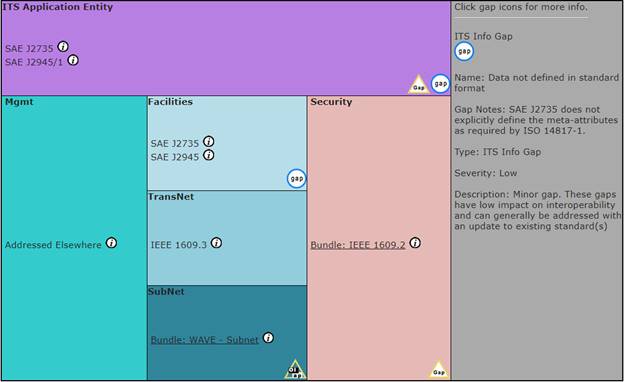
Figure 84. Communications Stack from Sample Project
An interface specification, which forms a part of project design, can be defined for any implementation, using these stacks and standards as the basis for that specification. In some cases, the specification may be quite simple, as the standards in question offer necessary definitions of dialogs, messages and data elements. In other cases, the specification will have to describe a great deal more, depending on the availability of necessary information.
5.3.6 Regional ITS Architecture Use Challenges and Solutions
Regions may need to address several challenges if the regional ITS architecture is to be used effectively to support project development. Across the country, regions are each encountering the same challenges and best practices are beginning to emerge that will encourage beneficial use of the architecture. Six challenges and their corresponding solutions are described below.
![]()
Challenge 1: While architecture maintenance responsibilities normally rest with a single agency, many agencies in a region are Project Sponsors that will need to use the architecture.
Solution: If it is to be used, the regional ITS architecture must be readily available to all Project Sponsors in the region. The latest version of the architecture should be available in a location readily accessible to all Project Team members. An architecture web page that provides access to the latest architecture information and resources is ideal. The form of the regional ITS architecture documentation should allow easy cut-and-paste into project documentation.
Challenge 2: Each of these Project Sponsor agencies has its own development process that must be adapted to use the regional ITS architecture if architecture use is to be systematic in the region.
Solution: The points at which the architecture should be used in project development should be formally documented for the state or region. In particular, an early checkpoint should be identified where the Project Team should have considered the architecture as the project scope is established so that integration opportunities are considered for each ITS project. A later checkpoint should be established where the Project Team should have verified that the as-designed project is consistent with the architecture and identified any regional ITS architecture changes that would be required to achieve this consistency.

Figure 85. Example Architecture Use Checkpoints
The FHWA/FTA Division Office can assist project teams with defining these points in the process, integrating architecture use requirements with existing federal oversight requirements. Such top-down inclusion is an effective way to ensure systematic architecture use by all Project Sponsors in the region.
Challenge 3: The Project Manager and Project Team may have little or no experience with the regional ITS architecture. While the architecture development process is inclusive, smaller agencies may not have participated, and only a few individuals from participating agencies actually develop expertise with the architecture. Staff turnover can further dilute architecture expertise over time.
Solution: Although not everyone will be an architecture expert, at least one member of every Project Team must be able to effectively use the architecture. If the Project Team does not have this expertise, then technical assistance should be provided by the Architecture Maintainer, FHWA/FTA Division office, or another resource to identify the relevant portion of the architecture for the project. To facilitate architecture use, the region should make the architecture as easy to use as possible, document instructions for use in project implementation, and make technical assistance and training available to Project Teams.
The architecture documentation should be reviewed with a critical eye towards ease of use by Project Teams and revised as necessary to better support this critical use. Regions may find that their architecture is technically sound but should be revised so that it can be more easily used by Project Teams. In particular, it should be easy for users to navigate from one part of the architecture documentation (e.g., a particular inventory element) to other related parts (e.g., functional requirements, stakeholders, and interfaces).
![]() The
architecture should be supported by a roadmap for architecture use that can be
used by each Project Team. The roadmap for architecture use includes
step-by-step instructions for how the region's architecture documentation
should be used for project development.
The
architecture should be supported by a roadmap for architecture use that can be
used by each Project Team. The roadmap for architecture use includes
step-by-step instructions for how the region's architecture documentation
should be used for project development.
RAD-IT can be used to identify the portion of the regional ITS architecture that is included in a project, if the Project Team has access to the tool and is familiar with its use. While this is an excellent way to use the architecture, it is unlikely that every Project Team will have access to the RAD-IT software or be able to use it without some training.
This is where having the relevant connection from the Regional ITS Architecture to the project readily available in a web-based version of the architecture.
![]() Ease
of use should be coupled with an effective technical assistance program that
allows Project Teams to get the assistance that they need when they have a question
about architecture use. As technical assistance is requested and provided, it
is a good idea to continue to enhance the documentation available to every
Project Team with a set of frequently asked questions and answers that can
further facilitate future use.
Ease
of use should be coupled with an effective technical assistance program that
allows Project Teams to get the assistance that they need when they have a question
about architecture use. As technical assistance is requested and provided, it
is a good idea to continue to enhance the documentation available to every
Project Team with a set of frequently asked questions and answers that can
further facilitate future use.
Larger agencies should consider having an ITS specialist that can participate on ITS-related Project Teams and support architecture use as well as appropriate application of the systems engineering process and ITS standards. The ITS specialist becomes another specialist in the range of environmental, legal, and technical experts that are included on the Project Team, depending on the type of project.
Training in the region's ITS architecture, with focus on how to use the regional ITS architecture, should be available to Project Sponsors. The architecture use sections on the ARC-IT website and the online training courses available on the ARC-IT website include general information on architecture use that could be used as a starting point and tailored to focus on the region's architecture and ITS project development process.
To ensure expertise by consultant members of the Team, include RFP requirements for knowledge/experience with regional ITS architecture and its use in ITS project procurements.
Challenge 4: ITS projects are location specific and the regional ITS architecture is normally defined at a higher level. For example, many different projects may implement field equipment that is generally represented with a single inventory element in the regional ITS architecture as shown in the comparison of Washington State DOT regional ITS architecture inventory elements with Washington State DOT transportation projects. As shown, there are many projects that are implementing transportation improvements in the region covered by the two WSDOT field equipment elements.

Figure 86. Architecture and Location-Specific Projects
Solution: In order to effectively use the architecture, the Project Team must bridge the gap between the higher-level regional ITS architecture and the relatively specific definition of a particular project. The different levels of abstraction are a potential stumbling block that should be addressed in the region's guidance for architecture use. For example, the project block diagram in a concept of operations may be more specific than what is represented in the regional ITS architecture, but still traceable to the regional ITS architecture.
While
it is sometimes beneficial, you should proceed with caution when adding detail
to your regional ITS architecture so that it more precisely depicts individual
projects. For example, a city may deploy field equipment with ten different projects
over the course of several years. It is probably a mistake to include ten
different inventory elements in the regional ITS architecture that specifically
represent the equipment in each anticipated project. This would add too much
detail to the regional ITS architecture and make it more difficult to maintain.
But listing the ten projects separately in the architecture and mapping each to
the same service packages can provide a good link from the general to the
specific implementations.
Challenge 5: Some ITS projects do not use the Highway Trust Fund and are not subject to the Regulation/Policy requirements. Projects developed exclusively with state or local funds and projects developed by non-transportation agencies (e.g., public safety agencies) fall into this category. For these projects, use of the architecture is strictly voluntary and can only be motivated by the potential benefits of use.
Solution: Information on the benefits of architecture use should be available to every project sponsor, not only those who sponsor projects that use the Highway Trust Fund. Some agencies, such as Virginia DOT, have developed a user guide that encourages architecture use for ITS projects, whether or not Highway Trust Funds are used. To coordinate public safety projects, the San Diego Association of Governments (SANDAG), the San Diego MPO, has established a public safety committee that coordinates planning for public safety integration projects with SANDAG. The architecture maintenance activity should periodically update the architecture to reflect other ITS projects that have been implemented so that the architecture continues to accurately reflect ITS implementation in the region.
Challenge 6: Some common projects that are categorized as ITS, like signal synchronization projects, impact only a single agency system and have lesser need to use the regional ITS architecture.
Solution: The purpose of the architecture use and systems engineering analysis requirements for ITS projects is to reduce technical risk and increase the likelihood of project success. Since the inherent risk in an ITS project varies significantly depending on the nature of the project, the Regulation/Policy allows the systems engineering analysis to be tailored commensurate with project scope. Projects that will benefit most from architecture use include:
- Multi-modal or multi-jurisdictional projects that connect systems from different agencies.
- New system developments that must consider future integration requirements.
Projects that are inherently limited in scope will benefit less from architecture use, such as:
- Installation of isolated rural traffic signals and other projects that have no reasonable opportunity for future integration
- System expansions that add no new interfaces and no new functionality (e.g., adding additional CCTV cameras to an existing system)
- Projects that enhance current system operation, but add no new interfaces or functionality (e.g., signal synchronization projects)
There is some potential benefit from architecture use on even the simplest ITS projects. For example, signal synchronization projects may benefit from architecture use in regions where integration of adjacent traffic signal systems is planned. The FHWA/FTA Division Office determines how the Regulation/Policy should be applied to different types of ITS projects in the region. For example, the California Division Office has established oversight procedures that require architecture use for all ITS projects, but only require direct oversight for higher risk "major" ITS projects. Some regions have established graduated processes where more detailed architecture use is suggested for more complex projects. An early project initiation checkpoint should include information about the project that allows project type and complexity to be determined so appropriate architecture use and systems engineering analysis processes can be defined.
5.4 Project ITS Architectures
The definition of a Project level ITS architecture, taken from 23 CFR 940 on Intelligent Transportation System Architecture and Standards is "a framework that identifies the institutional agreement and technical integration necessary to interface a major ITS project with other ITS projects and systems".
A project ITS architecture contains similar components to a regional ITS architecture, except the scope of it is a single ITS project, and the life cycle of the project architecture concludes with the completion of the project.
There are two related ways to develop a project ITS architecture:
1. As part of a regional ITS architecture development, by creating projects within the Regional Architecture Development for Intelligent Transportation (RAD-IT) software tool
2. As a more detailed architecture created in the Systems Engineering Tool for Intelligent Transportation (SET-IT), that may optionally be linked to the corresponding project in RAD-IT.
5.4.1 Purpose of a Project ITS Architecture
The purpose of developing a project ITS architecture is to illustrate and document, in the context of a regional ITS architecture, a representation of the project that can be used to support systems engineering outputs for the project, including the systems engineering analysis requirements defined in 23 CFR 940.11.
5.4.2 Components of a Project ITS Architecture
A project ITS architecture can be described by the following set of components:
- Stakeholders
- Operational Concept (user needs plus stakeholder roles and responsibilities)
- ITS Services (both existing and planned)
- Elements (or systems used to deploy ITS services)
- Interfaces supporting the services
- Agreements existing or planned to support the project
- System functional requirements
- ITS Standards applicable to the project
The components listed above apply to both approaches to developing a project ITS architecture listed above. The difference will be in the level of detail the project ITS architecture contains for some of the components such as requirements, interfaces, and ITS standards, and the corresponding value provided to architecture users. Each component above is linked to a separate page that explains the nature of the component when the project ITS architecture exists within a RAD-IT file, and then the additional level of detail for that component that can be created if the project ITS architecture is created using SET-IT.
Architecture Reference for Cooperative and Intelligent Transportation (ARC-IT) is used as a template to create project ITS architectures that are tailored for a specific ITS project. ARC-IT provides the fundamental building blocks: the physical objects (subsystems and terminators), interfaces (as defined by the information flows), service packages, user needs, etc., that are selectively included in the project ITS architecture and customized as necessary to fully reflect the details of the project.
5.4.2.1 Project Scope
Project Scope is a concise description of the project. It may be augmented by additional information about the project as described below.
5.4.2.1.1 Details Defined in RAD-IT
 The information about
project scope can be found on the Start page of RAD-IT when the project is
selected on the left side of the Start page (see figure below). In addition to
the project description, the start page includes a definition of the geographic
and scope of services for the project.
The information about
project scope can be found on the Start page of RAD-IT when the project is
selected on the left side of the Start page (see figure below). In addition to
the project description, the start page includes a definition of the geographic
and scope of services for the project.
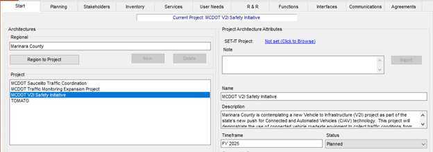
Figure 87. Project Architecture Start Tab in RAD-IT
5.4.2.1.2 Details Defined in SET-IT
The key information about project
scope is contained on the Overview Project page. As shown on the page, the
project has a name and description along with the following information:
- Geographic Scope: this is a text box to put where will the project be deployed
- Services Scope: this is a text box to describe what are the key ITS services that will be deployed
- Procurement Strategy: this is a text box to add a description of the procurement strategy applied to the project
- Operations Resources: this is a text box to add a description of the operations resources that will be required once the project is deployed.
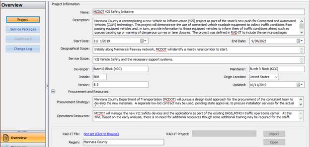
Figure 88. Project Information for Sample Project in SET-IT
5.4.2.1.3 Using the Component
The Project scope information contained in either RAD-IT or SET-IT can be used in documentation about the project, such as the Concept of Operations. The additional information that can be entered into the SET-IT Overview (Procurement Strategy and Operations Resources) can be used to address two requirements of 23 CFR 940.11 systems engineering analysis, which requires the following be identified:
- Procurement options;
- Procedures and resources necessary for operations and management of the system.
5.4.2.2 Stakeholders
Stakeholders are the agencies and organizations that own, operate, maintain or use the ITS systems that are a part of the project. These stakeholders could include both public and private organizations.
5.4.2.2.1 Details Defined in RAD-IT
The key information about stakeholders is
contained on the Stakeholders tab of RAD-IT. As shown on the tab, each
stakeholder has a name and description. The Stakeholders
tab on RAD-IT is shown below and is the tab where the initial updates of
stakeholder names or descriptions are performed.

Figure 89. Project Architecture Stakeholders Tab in RAD-IT
Stakeholders are mapped to several other components of the architecture. The updates of each of these components will require that their mapping to stakeholders is also updated. Based on the way RAD-IT works, an update to stakeholder information on the Stakeholders Tab will automatically be updated in the mapping to stakeholders on the other tabs.
The key outputs used to discuss stakeholders are either a table, which can be created by going to the RAD-IT top menu Output/Tables and selecting the Stakeholder Table shown below, or going to the Stakeholders tab on an architecture website.

Figure 90. Output Tables Menu in RAD-IT
Create a Stakeholder Group when you want to associate more than one
stakeholder with the same element. This could be a group of stakeholders, such
as several emergency services agencies, that may be in charge of an emergency
center in the Regional Architecture which is actually a group of emergency centers.
On the Stakeholders tab of RAD-IT, individual stakeholders are represented by
the single person icon while stakeholder groups are shown using the multiple
person icon.
5.4.2.2.2 Details Defined in SET-IT
The key information about Stakeholders is contained as a left tab on
the Definitions section of SET-IT. As shown on the tab, each stakeholder has a
name and description. With regards to stakeholders, the information is SET-IT
is comparable to that contained in RAD-IT. But the list of stakeholders in
SET-IT may be larger based on the different level of details in the elements
and interconnections that can be created in SET-IT.

Figure 91. Stakeholders Grid for Sample Project in SET-IT
5.4.2.2.3 Using the Component
Stakeholder information, either from RAD-IT or SET-IT, would most likely be included as part of the Concept of Operations document. The list of stakeholders and their description are also one of the inputs that would be used to complete the Stakeholder Roles and Responsibilities aspect of the 23 CFR 940.11. Note that SET-IT includes the capability to produce a draft Concept of Operations, and will by default include all stakeholder definitions in that output.
5.4.2.3 User Needs
A user need is a capability that is identified to accomplish a specific goal or solve a problem that is to be supported by the system.
5.4.2.3.1 Details Defined in RAD-IT
The key information about User
Needs is contained on the User Needs Tab of RAD-IT. As shown on the tab, the
user needs are associated with each service package that is a part of the
project. The original set of user needs are taken from ARC-IT. In RAD-IT you
select which of those apply, you can also create new needs relevant to the
service.
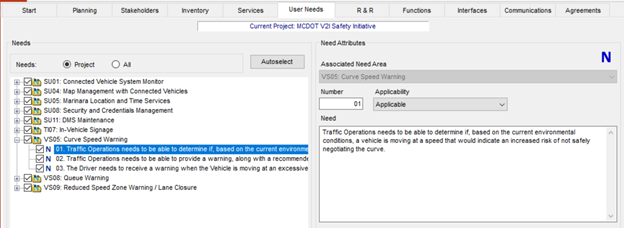
Figure 92. Project Architecture User Needs Tab in RAD-IT
5.4.2.3.2 Details Defined in SET-IT
The key information about User Needs is found on the Needs tab on the
Definitions section of SET-IT. As shown on the tab, each user need is organized
by service package. As is the case with RAD-IT, you can add user needs beyond
those in ARC-IT. The one aspect of user needs in SET-IT
that goes beyond the information in RAD-IT is that each user need can be
assigned a priority. The default is low/medium/high as well as Not Applicable.
This feature allows you to prioritize the user needs in relation to your
project.

Figure 93. User Needs Definitions Grid in SET-IT
5.4.2.3.3 Using the Component
Getting stakeholder agreement on a project's needs is essential to the successful completion of every project. The user needs contained in either RAD-IT or SET-IT can be used as a starting point for the development of an individual project's needs. SET-IT also includes the capability to produce a draft Concept of Operations that will take all the needs defined in SET-IT and organize them by service in the chapter on Justification for and Nature of Changes. Note that SET-IT includes the capability to produce a draft Concept of Operations, and will by default include all user needs in that output.
5.4.2.4 Roles and Responsibilities
Typical roles for transportation stakeholders include that they own, develop, operate, or maintain portions of the transportation system. Responsibilities cover activities that the stakeholders engage in as they perform their roles. An example of a responsibility is that a municipal agency operates traffic signal systems on arterials while a state agency operates detectors and signage on the freeway.
5.4.2.4.1 Details Defined in RAD-IT
The
key information about Roles and Responsibilities is
contained on the R&R Tab of RAD-IT. For a project, these roles and
responsibilities are typically a subset of the roles and responsibilities
defined for the regional ITS architecture. The figure below shows an example of
R&Rs from the sample project in RAD-IT.

Figure 94. Project Architecture R&Rs Tab in RAD-IT
Note that in RAD-IT the R&Rs tend to be "responsibilities" as defined above. An example responsibility from the figure above is that the Marinara County Department of Transportation has the responsibility for "Monitor traffic flow on the freeways. Determine travel times.". The R&Rs in RAD-IT can be output as a table from the Output pulldown, as shown in the figure below. The table can be organized by stakeholder or by Role and Responsibility (RR) Area, e.g., Freeway Management.

Figure 95. Roles & Responsibilities Output Tables Menu in RAD-IT
5.4.2.4.2 Details Defined in SET-IT
The key information about Roles and Responsibilities is found in the
Enterprise View, on the Stakeholder Roles tab on the Definitions section of
SET-IT. As shown on the tab, each stakeholder role is organized first by
stakeholder, then by role, then by element. The
information in SET-IT, since it is part of the Enterprise View, focuses on the
Roles (e.g. owns, operates, maintains) of the stakeholder with regard to the
specific elements. So, in the figure shown below, the Marinara County
Department of Public Works (MCDPW) installs, owns, and manages the MCDPW GARLIC
Information System.

Figure 96. Stakeholder Roles Definitions Grid in SET-IT
SET-IT allows you to create an output of these roles by selecting the Output Tables tab, the Elements Table from the Enterprise View, and then sorting the resulting table as shown in the figure. The information can also be obtained

Figure 97. Output Menu for Element Stakeholder Roles
5.4.2.4.3 Using the Component
5.4.2.5 Services
ITS services are transportation services upgraded or improved by the project. These services are deployed in order to meet operational goals and objectives of the region. In a project ITS architecture these ITS Services can be described by customized ARC-IT service packages, which identify the elements and information flows needed to provide each ITS service.
5.4.2.5.1 Details Defined in RAD-IT
The key information about ITS services is on the Services Tab in
RAD-IT. This tab shows which service packages are a part of the project.
Because of the high level nature of regional ITS architectures, many projects
are covered by one or two service packages in RAD-IT. The example below, from
the Sample architecture in RAD-IT, shows a more complex project that takes nine
service packages to full describe. For each service pacakge the elements that
are a part of the project's implementation of the service are identified.

Figure 98. Project Architecture Services Tab in RAD-IT
RAD-IT can output diagrams and tables related to the Service Packages for the project. The table below shows a portion of the output table for the Sample Project (SP) shown above.
Table 8. Example Project Service Package Output Table
|
SP # |
Service Package Name |
SP Instance |
Included Elements |
|
SU01 |
Connected Vehicle System Monitor |
Yes |
MC Field Maintenance Equipment |
|
MC Freeway Management Center (BASIL/PINCH) |
|||
|
MC IT Field Personnel |
|||
|
MCDOT CV Roadside Equipment |
|||
|
MCDPW GARLIC Information System |
|||
|
SU04 |
Map Management for V2I Safety Initiative |
Yes |
Digital Map System |
|
Equipped Vehicles |
|||
|
MC Freeway Management Center (BASIL/PINCH) |
|||
|
MCDOT CV Roadside Equipment |
|||
|
MCDPW GARLIC Information System |
|||
|
Traveler Information Devices |
|||
|
SU05 |
Location and Time Services for V2I Safety |
Yes |
Center Location and Time Source (LTS) |
|
Equipped Vehicles |
|||
|
Field Location and Time Source (LTS) |
|||
|
MC Freeway Management Center (BASIL/PINCH) |
|||
|
MCDOT CV Roadside Equipment |
|||
|
MCDPW GARLIC Information System |
|||
|
Position Correction Source |
|||
|
Traveler Information Devices |
5.4.2.5.2 Details Defined in SET-IT

Figure 99. Service Packages Menu Screen in SET-IT
While the diagram on the Overview page shows the ARC-IT service package diagram, the project ITS architecture is defined by customizing these ARC-IT diagrams for the specific elements and interfaces that apply to the project. Selecting the Diagrams tab provides a window to each of the customized service package diagrams that define the architecture. The figure below shows the example project implementation of the service package In-Vehicle Signage.
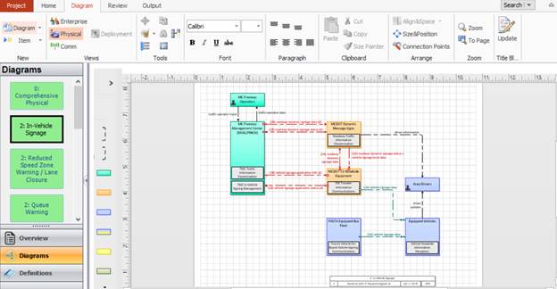
Figure 100. Service Package Diagram from SET-IT
Below is a larger version of the service package diagram. Note that for the project not all the elements and interfaces will be implemented. The diagram shows an interface between Pasta Equipment Bus Fleet and Equipped Vehicles, but does not include interfaces for Emergency Vehicles or Maintenance Vehicles, which are in the ARC-IT version of the service package. Also note that in the project ITS architecture the project elements are described with their connections. So for example, there an interface between MC Freeway Management Center and MCDOT Dynamic Message Signs, which are the elements that are being deployed for the project.
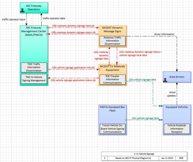
Figure 101. Service Package Diagram from SET-IT (Enlarged)
While SET-IT allows a project ITS architecture to be imported from RAD-IT, this usually serves as a starting point for creation of a more detailed project ITS architecture in SET-IT. The example project figure above includes additional details, such as the interfaces to Area Drivers and MC Freeway Operators, which would not be included in a regional ITS architecture.
SET-IT also provides the tools to specify details like the flow characterstics on each interface which will be discussed below. In SET-IT the user can also use the Sequence tool to document and show the sequence of steps that users might go through in a set of user scenaios. These scenarios can then be documented in the generated Concept of Operations.
5.4.2.5.3 Using the Component
A description, including diagrams or tables, of the project's services can be used in several aspects of projece development. Services are a key aspect of the CFR 940.11 systems engineering analysis (SEA) requirement relating to "Identification of portions of the regional ITS architecture being implemented", so you can use the information described in the RAD-IT or SET-IT sections above to partially address this SEA requirement. Some aspects of the services will likely be included in any Concept of Operations developed for the project, usually in the section relating to Justification for and Nature of Changes. A description, at a high level, of the new or revised services for the project is one of the best ways to describe the changes planned for the project. If a SET-IT file is created then the service package diagrams can provide a more detailed view of the changes. Note that SET-IT includes the capability to produce a draft Concept of Operations, and will by default include all project services in that output. In addition, the description of services should be included in the high level design document for the project. The high level design document should include a description of the project ITS architecture, using whatever information is available (from RAD-IT or SET-IT) and a description of the services, along with diagrams if available would definitely be a part of that description.
5.4.2.6 Elements
ITS Elements are the systems, or pieces of systems, that provide ITS services or share information as part of the ITS services. Each stakeholder agency, company, or group owns, operates, or maintains ITS systems in the region. Each project ITS architecture has a list of elements (called an inventory) which may also include non-ITS elements that provide information to or get information from the ITS elements.
5.4.2.6.1 Details Defined in RAD-IT
The key information about
the ITS elements can be found on the RAD-IT Inventory tab, where the names,
descriptions, associated stakeholder, status and mapping to ARC-IT components are
contained. The Inventory Tab on RAD-IT is shown below for a project in the
sample database.

Figure 102. Project Architecture Inventory Tab in RAD-IT
The most common output from RAD-IT for the elements is a table from the Output Tables, see the figure below. When creating an output table, a common approach is to create one sorted by Stakeholder, as shown in the figure below.

Figure 103. Output Menu for Element Inventory
5.4.2.6.2 Details Defined in SET-IT
Information about which Elements are a part of the project can be found
on the Elements table or grid in the Definitions menu area. This page shows a
list of all the elements in the project. The page shows basic information about
the elements, with additional information on the Details tab.
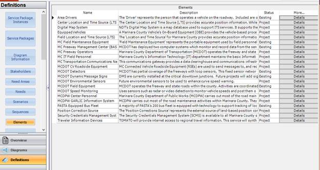
Figure 104. Elements Definitions Grid in SET-IT
Elements are also a key component of the Service Package diagrams that are part of the architecture. For example, the figure below shows the Queue Warning Service Package, with the elements of MCDOT highlighted in the diagram.
![]()
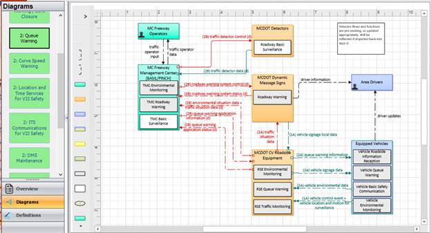
Figure 105. Service Package Diagram in SET-IT
The elements of the project
in SET-IT can be imported from the project in RAD-IT, and then augmented to
create a more detailed architecture for the project. The example above includes
the elements MC Freeway Operators and Area Drivers that would usually not be
included in a regional ITS architecture.
5.4.2.6.3 Using the Component
5.4.2.7 Interfaces
Interfaces are the electronic connections between ITS elements, which support the exchange of information between ITS elements. Interfaces can be defined by at two levels as:
- Interconnects: Communications paths that carry information between elements. Some of the key types of communications links relevant to regional ITS architectures are Center to Center (C2C), Center to Field (C2F), Field to Field (F2F), Wide Area Wireless (WAW), and Short-Range Wireless (includes Dedicated Short Range Communications or DSRC).
- Information Flows: Information that is exchanged between elements. Information flows are a high-level description of the electronic information transmitted from one element to another. These information flows and their communication requirements define the interfaces which form the basis for ITS standards.
5.4.2.7.1 Details Defined in RAD-IT
The key information about
the interfaces can be found on the RAD-IT Interface tab, where the tool allows
the user to define the interfaces between the transportation system elements in
the project.
There are various views and customization options for this tab. The view below shows the information exchange tab, with some of the information flows between the MC Freeway Management Center and MCDOT field elements. For the information flows between elements, each information flow is described by a source element (where the information originates), a destination element (where the information is sent) and a descriptive name for the information itself. The high-level status of the information flow (e.g., existing, planned, future, etc.), and whether the project information flow is included in the regional ITS architecture. The page also indicates if there is a communications element defined in the project that supports the information flow on the interface.
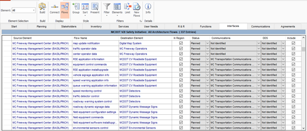
Figure 106. Project Architecture Inventory Tab in RAD-IT
5.4.2.7.2 Details Defined in SET-IT
Information about Interfaces that are a part
of the project can be found on the Definitions- Information Flow Triples selection. The
definitions of the Information flows can be found at Definitions-
Information Flows.
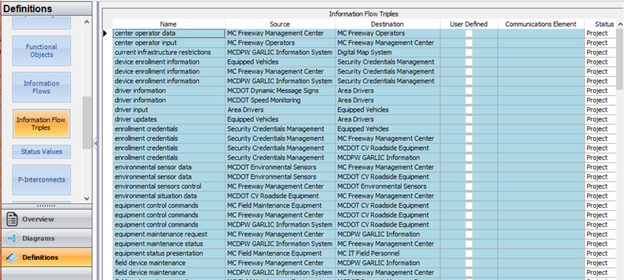
Figure 107. Information Flow Triples Definitions Grid in SET-IT
The Details tab on this latter page also provides considerable additional information about the characteristics of the information flow (e.g. time content, spatial content and cardinality) along with security considerations for the information flow defined by the Federal Information Processing Standards (FIPS) attributes of Confidentiality, Integrity and Availability.
The interfaces also play a key role in the service package diagrams. All the Information Flow Triples in the definition table show up in one or more of the Service Package Diagrams.
While the interfaces (and elements) imported from RAD-IT are a good
starting point for the definition of interfaces in SET-IT, take advantage of
the flexibility inherent in SET-IT to define new interfaces, or to add details
to the interfaces that are imported. The projects in RAD-IT are described at a
high level commensurate with the level of detail in a regional ITS architecture.
SET-IT can be used to add more details to the project ITS architecture that
provide a more complete description of the interfaces (and elements) that
makeup the project.
5.4.2.7.3 Using the Component
A description of the project's interfaces, either in tables or diagrams, can be used to support several aspects of project development. Interfaces are a key aspect of the CFR 940.11 systems engineering analysis (SEA) requirement relating to "Identification of portions of the regional ITS architecture being implemented", so you can use the information described in RAD-IT or SET-IT to partially address this SEA requirement. Interfaces will likely be included in any Concept of Operations developed for the project, usually in the section relating to Concept for Proposed System, which will discuss the new or revised interfaces to be implemented by the project. SET-IT supports the creation of a ConOps. In addition, the description of interfaces (and information flows) should be included in the high level design document for the project. The high level design should describe the project ITS architecture, using whatever information is available from RAD-IT or SET-IT, including the project's interfaces.
5.4.2.8 Agreements
To deploy the services defined for the project, agreements between stakeholders may be required especially when inter-jurisdictional interfaces are involved. The agreements may define the integration planned, the plans for maintaining and operating the elements and the funding responsibilities of the stakeholders.
5.4.2.8.1 Details Defined in RAD-IT
The Agreements Tab on RAD-IT is shown below and is the tab to use to
collect the list of existing agreements and the agreements potentially needed to
implement the project. Each list entry identifies the agreement title, the stakeholders
involved, the type of agreement that is anticipated, high level status
(existing or planned), and a concise statement of the purpose of the agreement.
The figure below shows a project in the Sample database with a planned
information exchange agreement between MCDOT and State Highway Patrol.
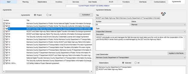
Figure 108. Project Architecture Agreements Tab in RAD-IT
5.4.2.8.2 Details Defined in SET-IT
Information about Agreements that are a part of the project can be
found on the Enterprise View, Definitions- Agreements page. The figure below,
for the SET-IT sample project, shows the similar information for an information
sharing agreement between MCDOT and State Police shown in the RAD-IT figure
above. In addition to a tabular description of the agreements, SET-IT has the
capability to create a high level enterprise view diagram showing in graphical
form the agreements, roles, and expectations that connect stakeholders
together.
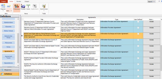
Figure 109. Agreements Definitions Grid in SET-IT
5.4.2.8.3 Using the Component
A description of the project's agreements can be used to support development of the Concept of Operations (ConOps) for the project. Agreements will likely be included in the section relating to Concept for Proposed System, which will discuss the agreements needed for the project. If the ConOps is developed based on a SET-IT file, then an Enterprise View, which includes agreements, may be a part of the outputs used in the ConOps. Note that SET-IT includes the capability to produce a draft Concept of Operations, and will by default include all the agreements in that output.
5.4.2.9 System Functional Requirements
Functional requirements are a high-level description of the required functionality for each ITS element to provide the ITS services that have been identified for the project. The functional requirements describe WHAT a system must do to provide the ITS services. As defined in the regional ITS architecture, these requirements are very high level. For a project ITS architecture, these are broken down into more detailed requirements to document fully the functionality of the system.
5.4.2.9.1 Details Defined in RAD-IT
The key information about system functional requirements is found on
the Functions tab of RAD-IT. As shown for the sample project below, for each
element there is a list of functional objects. This list is based on the
physical objects mapped to the element.
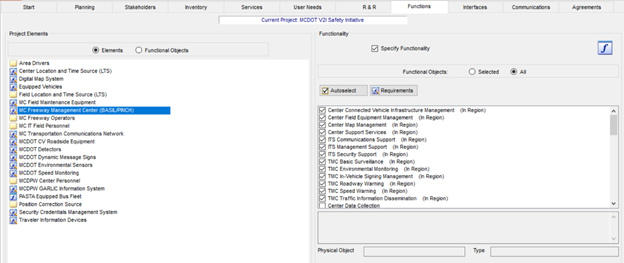
Figure 110. Project Architecture Functions Tab in RAD-IT
Selecting the Requirements button will open a new window that shows all the requirements defined for the selected Functional Objects. The figure below shows a subset of the Requirements for the element selected above. Note that some requirements are included and some are not, indicating that these requirements have been customized. Additional customization is allowed by tailoring requirements or creating new requirements.
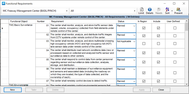
Figure 111. Functional Requirements Details Screen from RAD-IT
The functional requirements
in the project architectures in RAD-IT can be imported into SET-IT and used as
a starting point to create a more detailed view of requirements as discussed in
the Details Defined in SET-IT section below.
5.4.2.9.2 Details Defined in SET-IT
Information about requirements that are a part of the project can be
found on the Definitions- Requirements selection. This page shows a list of all
the requirements defined for the project. The page shows basic information
about the requirements similar to that shown in RAD-IT, including:
- the element the requirement applies to,
- functional object,
- requirement number,
- requirement text and
- whether the requirement is user defined, or taken from ARC-IT.
In addition, this tab includes additional information about the requirement including:
- Need addressed by the requirement- these originate as needs defined by Service Package, but can be revised to be user needs for the project.
- Source of the Requirement- most requirements originate with ARC-IT, but if you make the choice to create more detailed requirement, then these can be identified as developed for the project.
- Verification method for requirement- you have the ability to assign one of the four methods (analysis, inspection, demonstrate, or test)
The figure below shows the requirements defined for the sample project.
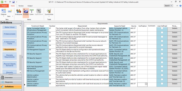
Figure 112. Requirements Definitions Grid in SET-IT
SET-IT has a second tab for requirements that show the requirements defined for each element.
5.4.2.9.3 Using the Component
A listing of the project's requirements can be used in several aspects of project development. Requirements are a key aspect of the CFR 940.11 systems engineering analysis (SEA) requirement relating to "Requirements definitions", so you can use the information described in the RAD-IT or SET-IT sections above to partially address this SEA requirement. Requirements are a key output of the systems engineering process, so any level of detail relating to requirements contained in RAD-IT or SET-IT can be used to begin the requirements development process. If more detailed requirements are defined or developed in SET-IT, then these can be used in the project development.
5.4.2.10 ITS Standards
ITS standards are documented technical specifications sponsored by a Standards Development Organization (SDO) to be used consistently as rules, guidelines, or definitions of characteristics. ITS Standards are primarily defined for interfaces between ITS elements, but they can also be defined for the physical characteristics of ITS elements as in the cabinet and traffic controller standards developed by NEMA and other organizations and SAE standards developed for motor vehicles.
5.4.2.10.1 Details Defined in RAD-IT
ARC-IT maintains a mapping of information flows to the collection of communications
protocols and data definitions that can be used to implement the information
flow. The Communications
View pages of the ARC-IT website include the latest mapping between ARC-IT
and the ITS communications solutions. RAD-IT accesses this mapping information
and makes it available for review and customization. The "Communications" tab
in RAD-IT provides the opportunity to decide which of the ITS Communications
Solutions best applies to the region. Use the Communications Tab in RAD-IT to
see the full list of communications solutions that are part of the architecture
and use it when there are unique situations for your region, e.g. your
state/region requires a certain standard interface for certain elements and you
need to show that at the regional level.
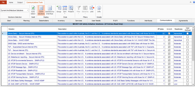
Figure 113. Project Architecture Standards Tab in RAD-IT
5.4.2.10.2 Details Defined in SET-IT
Information about standards
that are a part of the project can be found on the Comm View, which contains a
variety of information under the Definitions Tab. This tab contains the
following information about the communications solutions that can apply to the
project.
- Flow Triples to Solutions- a mapping of possible communications solutions to individual triples.
- Solutions- sets of standards that cover data definition, communications protocols, and security
- Standards- the individual standards that make up the communications solutions
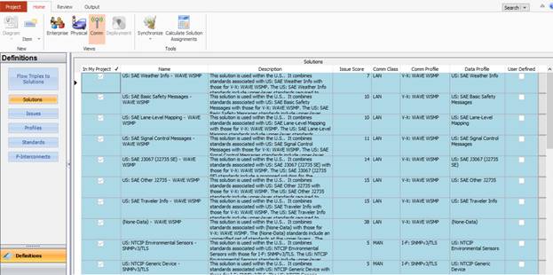
Figure 114. Project Communications View Tab in SET-IT
5.4.2.10.3 Using the Component[b3]
A description of the standards that are part of the communications solutions are a key aspect of project development. Definition of the standards is a requirement of 23 CFR 940.11 systems engineering analysis (SEA), which requires "Identification of applicable ITS standards and testing procedures", so you can use the information described in the RAD-IT or SET-IT sections above to partially address this SEA requirement (both tools identify standards, but not testing procedures).
One of the key parts of the systems engineering design step of the process is to identify interfaces and the standards that would be used to implement the interfaces. One of the key improvements of Version 9 in both RAD-IT and SET-IT is that rather than defining a flat set of standards, both tools define communication solutions that consider the set of standards needed to implement a triple in the project.